Quantcast
Channel: Dave Richards AA7EE
Viewing all 99 articles
Browse latest View live

The Sproutie “SPT” Beacon – A Legal, Unlicensed HiFER Beacon

$
0
0

Note – this blog-post discusses the use of the 13553 – 13567KHz band under FCC Part 15 regulations in the US. Although it is a worldwide allocation, rules vary according to where you are. Off the top of my head, I do know that there are HiFER beacons operating in some countries on the European continent, but that is the extent of my knowledge of this type of operation outside the US.

Before saying anything else, I must note that even though the earlier projects which were named after my cats were not my designs, I did at least contribute enough of my own input that I could perhaps get away with naming them. I’m not sure that is the case with this venture, as I simply re-purposed it for a slightly different band and usage. However, the urge to name things around here after my cats is strong, so what I am calling The Sproutie Beacon, is really an original Hans Summers QRSS TX, modified slightly for the 15553 – 13567KHz HiFER band.

I have long been fascinated with clandestine and pirate radio stations. The UK has a long and hallowed history of pirate operation, since Radio Caroline and the other pirate ships began to grace the airwaves in the 1960’s. When I was in my teens in the 70’s, Caroline was still on the air, as was a newcomer to the pirate ship scene, a station called Laser 558. Laser 558 was, like the other pirate ships before it, stationed just outside British territorial waters, in international waters. It differed from the other pirates in one very noticeable detail though – it had American DJ’s, and was programmed like a US Top 40 station. To a British listener who was used to DJ’s talking quite a lot, the sound of American accents and near-continuous music, as dull as it might sound to a Stateside listener, was quite thrilling to these teenage British ears in the 1980’s. London is well-known for it’s many land-based pirate broadcasting stations on the FM band, but there weren’t too many outside the big cities. As a teen in the 80’s growing up in the Midlands, we did have a fairly high-powered pirate station on the AM MW broadcast band, with a wide coverage area, called Sunshine Radio, which I enjoyed listening to greatly.

When living in Los Angeles in the 1990’s, I was asked to DJ on a local FM pirate by one of the resident presenters, but politely declined, as I was already working in my chosen career, doing DJ, voice-over and production work. I was getting my DJ jollies for about 50 hours a week – and getting paid for it at that point, so said no to an opportunity that a few years earlier, I would most likely have jumped at. Los Angeles was not known for pirate activity at all – the area was almost entirely devoid of it, but this one station was a notable exception. It was known as KBLT. The founder, Sue Carpenter, even wrote a book about it, called “40 Watts From Nowhere”. Written from her perspective, and relating the trials and tribulations of running a pirate radio station that was on the air nearly 24/7 out of her apartment in the Silverlake district of Los Angeles, it’s a good read for anyone interested in the subject of pirate broadcast stations.

Then, in 2008, after moving to San Francisco, I was tuning around the shortwave bands in CW mode from my apartment in Ocean Beach one day, and heard a series of dits on approximately 4096KHz, Further investigation revealed that it was one of a cluster of unlicensed (and not legal) beacons operating from various locations in the California deserts on various frequencies centered around ~4096/4077KHz and 6626KHz with powers of the order of a few 100mW’s. All of them operated from solar power. Some also had batteries and could transmit 24/7, while others had only solar panels and were daytime only beacons. Even Jason NT7S could hear one of them from his QTH in Portland, Oregon – propagation was good on a regular basis back then. There are a number of these beacons, most of them in the deserts of the south west. Some send dits at various speeds, some send letters in Morse code. There is also one that sends the ambient temperature in Morse. They are discussed, with reception reports, over on the HF Beacons forum at HF Underground.

If, from all of this, you conclude that I would still be interested in running some kind of pirate operation, you’d be partially correct. I say partially because, in truth, although I enjoy listening to the clandestine activities of others, I wouldn’t want to do anything that might, even in theory if not in practice, jeopardize my ham license. I’d love to take a QRP solar-powered HF beacon out into the desert and leave it there, sending it’s valiant little signal, day after day, year after year, and checking the online reception reports from time to time. It would be interesting to see how long it would last. I read a report from someone who did install such a beacon, and his description was quite lyrical. He described how, whenever he was out hiking, fishing, or otherwise enjoying the great outdoors, he would take his portable shortwave radio and listen out for his beacon, thinking of the little transmitter out in the remote desert, courageously sending it’s diminutive signal across the great expanses of wilderness. Very evocative stuff.

It turns out that there is a way to operate an unmanned beacon on the HF bands below 28MHz, and to do so legally. The details, in the US, are contained within the FCC Part 15 regulations. These are the regulations which set out the requirements for unlicensed transmitters, among them baby monitors, cordless phones, toy walkie talkies, garage door openers, WiFi and Bluetooth devices, to name a few. In much of the spectrum in which operation is allowed, the power limits are very low, though there are a few bands where the allowance is more generous. The band with the most easily-attainable DX potential is the 14KHz-wide ISM band centered around 13.56MHz. Power limits are specified not in terms of the device output power, but as a maximum field strength at 30 meters. Medical diathermy machines operate in this band hence, I presume, the reason for a field strength stipulation rather than actual power into an antenna. This band is also inhabited by RFID devices. If you listen, you may well hear a variety of odd beeps and carriers, particularly near the center frequency of 13.56MHz. The maximum field strength allowed under FCC Part 15 regulations is 15,848 microvolts/meter at 30 meters. Few among us have access to accurate field strength meters, but John W1TAG has written this very informative paper, in which he runs the calculations, and comes to the conclusion that 2.3mW into a ground plane, or 4.6mW into a dipole would produce the maximum allowed field strength. Now 4.6mW isn’t a whole lot of power, but the WSPR and QRSS folk will tell you that DX results can be had, even within those limitations. In fact, the beacon activity on this band is divided between folk who run beacons sending CW at speeds that can be read by ear, and QRSS transmissions. A few people do run grabbers on this band, and report the results. Beacon activity in this ISM band is a very niche pursuit, but there is a good discussion forum over at the Longwave Message Board. As the title suggests, this site was set up for LF operators, but there is HiFER discussion there too,

My first “proof of concept” at putting together a beacon for this band was to connect an N0XAS PicoKeyer in beacon mode to my Pixie 2 transmitter. With the PiicoKeyer, if you insert the prosign BN at the end of stored message #1, it will automatically repeat. Unfortunately, my older version of the PicoKeyer will not power up again in beacon mode if power is lost. This was taken care of in later versions, but it meant that I wouldn’t be using this particular version of the PicoKeyer in the final version of the beacon. My Pixie 2 put out about 170mW on it’s original frequency of 7030KHz when powered by 12V, but this dropped to an encouraging 5-10mW at 3.6V (3 x 1.2V NiMH cells in series).

For the final version, I wanted all the electronics to be on one single board. At that point, I was thinking about purchasing a PicoKeyer chip from N0XAS and building the keyer, Manhattan-style onto the same board as a Manhattan-built transmitter. Then I remembered the Hans Summers QRSS Transmitter that I had built a few years ago. After a brief flirtation and a lot of fun with QRSS on 30M, the board sat languishing in a box. A little experimentation showed that it would still work down to voltages below 5V, and with the drive trimpot, I figured I’d be able to adjust the drive to give an appropriately low output power. Even better was the fact that on the QRP Labs website, there were details of a mod by Aldo IW2DZX for altering the output from FSK to straight on-off modulation, which I happened to want with this beacon.

Getting the QRP Labs QRSS TX on the HiFER band was straightforward. A pack of 5 x 13.56MHz crystals was purchased from an eBay seller. I chose HC49/U crystals over the more popularly available HC49/S, as I have read that the former tend to pull over a wider frequency range, due to the crystal cut. Receiving this pack of crystals in the mail was exciting. Think of the possibilities!

Here’s the final schematic for Hans’ little beacon transmitter, modified for straight on-off keying, and with values appropriate for the 13553 – 13567KHz HiFER band –

original25


The jumpers on pins 5, 6 and 7 of the ATtiny13 are used for programming the sending speed. Refer to the original kit instructions for programming the speeds. Hans’ firmware allows 6wpm, 12wpm, and 6 QRSS speeds ranging between QRSS1 (1 second dits) and QRSS20 (20 second dits). The original schematic didn’t include the 3 x 10K pull-down resistors on these pins. I included them, as my TX wasn’t transmitting the selected modes. If these pins are left without pull-down resistors, then an unconnected pin might be incorrectly interpreted as “high” by the chip. The original circuit used a reverse-biased red LED to provide frequency-shift keying. This was removed, along with a 470K resistor and a “gimmick” capacitor, and a 2N3904 transistor, 22K resistor, and 0.1uF capacitor added to key the PA transistor. Also changed were the values of inductance and capacitance in the output low-pass filter. To cap off the mods, a 3.3V regulator was added. Because of the strict power limitations on this band, I wanted to ensure that the TX was running close to the maximum allowed power at all times, with minimal variation due to power supply fluctuations.

Although I modified my existing QRP Labs original QRSS transmitter, if you don’t have one to modify, you could build it from the schematic above, Ugly-style or Manhattan-style. A little transmitter built using MeSQUARES and MePADS would look quite nifty, methinks. The values in the schematic are the final values for the HiFER band. If you decide (with the help of the info on Hans’ site) to build it for QRSS operation as an MEPT on a ham band, you can run it from 5 – 6V for increased TX power output. I believe it can put out up to 150mW. On the HiFER band, of course, we don’t want anywhere near that much power, so a 3.3V regulator does the trick nicely.

Here is a top view of the modified board, with both new inductor and capacitor values for the HiFER band, and the IW2DZX mod for straight on-off keying completed. The speed selection jumper holes to the right of the ATtiny chip have been drilled out to accept a header block. With the original TX, you had to solder a wire between 2 holes to select a given speed. Now, the speed selection is accomplished by plugging in a jumper block (or a combination of jumper blocks). You can also see the 3.3V regulator at the far left edge of the board, in the middle. 3 old parts to the left of the trim cap have been removed, and 2 new ones added. I’ll leave you to figure out what they are :-)  –

original8

The underside of the board, showing the extra transistor (a 2N3904) for the straight on-off keying mod. You can also see the 3 x 10K pull-down resistors, as well as a 1pF NPO capacitor added across the trimcap to tweak the frequency coverage.  The new values of capacitors required in the output low-pass filter were larger than I had on hand, so I made them up by placing smaller values in parallel. You can see 2 of those parts in the photo, placed on the underside of the board, in parallel with capacitors on the topside. I cleaned the board with flux cleaner, but ended up with a white residue. Not sure what it is. It bugs me, but I decided to let it go –

original9

A few more views of the board –

original10

original15

original11

original12

original13

If at this point, you don’t have a functioning keyer chip, you can verify that the transmitter is working by connecting pin 3 of the DIP socket to pin 8 (the +3.3V supply), which will activate the keying transistor and turn the PA on. You can listen to the little transmitter on a nearby receiver, or look at the output on an oscilloscope (or both).

Now to decide on a callsign, or other beacon ID that you want to send. There are no ID requirements when operating under Part 15 regulations. Indeed, this band isn’t even intended for these types of communications, though this usage does fall within the rules. This leaves you, the fledgling HiFER control operator, free to transmit any ID you want. I decided that I wanted the letters “SPT” in honor of my youngest kitty, Sprout. But how to go about changing the firmware? This was no mean feat for a person like myself, who has studiously avoided all types of non-analog electronics my entire life.

This next part of the narrative will be blindingly simple for many, but is directed at people like myself, who are fairly new to the task of compiling and flashing code to a micro-controller. You have to search around a bit to find this fairly basic information in a form that we newbies can understand, so I thought I’d attempt to provide a tutorial of sorts here. For those who know what they’re doing in this area, please feel free to add comments and correct me.

The code, written in C, is posted on Hans’ personal site here. The general page on the keyer chip on his site is here. By the way, if you haven’t seen Hans G0UPL’s personal site, you’re in for a treat. It’s a treasure trove of personal projects and just screams “home-brewer/experimenter”. There are many happy evenings of reading on it!

Somewhere online, (in a Yahoo group, I think), I read a message from Yan XV4Y to the effect that he hadn’t been able to compile Hans’ code, and had made a slight modification to it to correct that, as well as making an addition, to allow spaces to be included in the sent message. Later, Hans told me that he had been using Atmel Studio 4 on an older version of Windows, and that it was possible that some folk might have had trouble compiling it with newer programs. He also said that he wasn’t sure whether the code on his site had been updated or not.  I sent an e-mail to Yan, asking if there was any chance of him sharing his code with me. He responded very quickly in the affirmative, and also said it was fine for me to share it here. Please note that Hans’ code, as posted on his site, may very well compile and work fine. It’s just that I used Yan’s version. Yan was quick to point out that this is really Hans’ code with just a few minor mods from him. Many thanks to Hans for allowing me to post it here, and to Yan for allowing me to post his slightly modified version. For the slightly clueless people like me, the instructions at the beginning tell you what to do in order to insert your own custom callsign. For the record, Yan said that this code compiles perfectly on Mac OS X with Xcode using Crosspack-AVR. I’m a Windows person, so I’ll relate it the way I did it. In the following piece of beacon code, I set the callsign to be GRC. If you’re a fan of grilled cheese sandwiches and bacon, the idea of a “grilled cheese beacon” might be appealing, hence the callsign GRC. I know it’s a bit corny, but it will suffice for this example –

// This is an amendment to the beacon program written by Hans Summers
// G0UPL. It adds the facility for a space character to be embedded
// within the transmitted callsign character string
//

// To change the callsign string you have to :-

// alter #define MSGMAX to the length of the callsign string +1

// insert the callsign you want, ensuring each character is seperated by a space
// into the text between the curly brackets after int8_t msg[MSGMAX] ending the string with a _SPC

//  e.g. for AB4CDE

// #Define MSGMAX 7


// int8_t msg[MSGMAX] = { A B _4 C D E _SPC };

// e.g. for PA5D M M

// #Define MSGMAX 9

// int8_t msg[MSGMAX] = { P A _5 D _SPACE M _SPACE M _SPC };


#include <avr/io.h>
#include <avr/interrupt.h>

volatile uint8_t msgIndex;
volatile uint8_t timerCounter;
volatile uint8_t counter2;
volatile uint8_t audio;
volatile uint8_t key;
volatile uint8_t bit;
volatile uint8_t pause;
volatile uint8_t character;
volatile uint8_t speed;
volatile uint16_t callsign;
volatile uint8_t keyDelay;

#define PERIOD 6

#define A		0b11111001,
#define B		0b11101000,
#define C		0b11101010,
#define D		0b11110100,
#define E		0b11111100,
#define F		0b11100010,
#define G		0b11110110,
#define H		0b11100000,
#define I		0b11111000,
#define J		0b11100111,
#define K		0b11110101,
#define L		0b11100100,
#define M		0b11111011,
#define N		0b11111010,
#define O		0b11110111,
#define P		0b11100110,
#define Q		0b11101101,
#define R		0b11110010,
#define S		0b11110000,
#define T		0b11111101,
#define	U		0b11110001,
#define	V		0b11100001,
#define	W		0b11110011,
#define	X		0b11101001,
#define	Y		0b11101011,
#define	Z		0b11101100,
#define _SPACE  0b11101111
#define _SPC	0b11101111
#define _0		0b11011111,
#define _1		0b11001111,
#define _2		0b11000111,
#define _3		0b11000011,
#define _4		0b11000001,
#define _5		0b11000000,
#define _6		0b11010000,
#define _7		0b11011000,
#define _8		0b11011100,
#define _9		0b11011110,
#define _BRK	0b11010010,
#define _KEYUP	0b10000000
#define _KEYDN	0b10100000

#define MSGMAX 4
#define SHORTSTART 0
int8_t msg[MSGMAX] = { G R C _SPC };

uint8_t speeds[8] = {1, 2, 10, 30, 60, 100, 150, 200};
uint8_t dit[8] = {150, 150, 150, 150, 150, 150, 150, 150};
//uint8_t speeds[8] = {1, 1, 1, 10, 30, 60, 100, 200};
//uint8_t dit[8] = {150, 36, 30, 150, 150, 150, 150, 150};
// DIT 		SPEED	WPM
// 150 		1		12wpm
// 150		2		6wpm
// 150		10		QRSS1
// 150		30		QRSS3
// 150		60		QRSS6
// 150		100		QRSS10
// 150		150		QRSS15
// 150		200		QRSS20
// 36		1		50wpm
// 30		1		60wpm

int main(void)
{
	DDRB = 24;

	TCCR0B |= (1<<CS01) | (1<<CS00);	// Prescale by 8
	TIMSK0 |= (1<<TOIE0);
	msgIndex = 0xff;

	sei();

	while(1);

	return 0;
}

ISR(TIM0_OVF_vect)
{
	audio++;

	if (audio == 1)
	{
		if (key) PORTB |= 0x08;
	}
	else
	{
		PORTB &= ~(0x08);
		audio = 0;
	}

	// 1500Hz here
	timerCounter++;

	if (timerCounter == dit[speed])
	{
		// 10Hz here
		timerCounter = 0;
		callsign++;

		if (keyDelay)
			keyDelay--;
		else
		{
			counter2++;
			if (counter2 >= speeds[speed])
			{
				counter2 = 0;

				if ((character == _KEYDN) || (character == _KEYUP))
				{
					key = 0xff;
					bit = 0;
				}
				else
				{
					if (!pause)
					{
						key--;
						if ((!key) && (!bit)) pause = 2;
					}
					else
						pause--;
				}

				if (key == 0xff)
				{
					if (!bit)
					{
						msgIndex++;
						if (msgIndex == MSGMAX)
						{
							msgIndex = SHORTSTART;
							if (callsign > 6000)
							{
								msgIndex = 0;
								callsign = 0;
								speed = 0;
							}
							else
							{
								msgIndex = SHORTSTART;
								speed = (PINB & 0x07);
							}
						}

						bit = 7;
						// Get character from message
						character = msg[msgIndex];
						// Look for 0 signifying start of coding bits
						while (character & (1<<bit))
						{
							bit--;
						}
					}

					bit--;

					if (character == _SPC)
						key = 0;
					else if (character == _KEYDN)
						key = 1;
					else if (character == _KEYUP)
						key = 0;
					else
					{
						key = character & (1<<bit);

						if (key)
							key = 3;
						else
							key = 1;
					}

					if ((character == _KEYDN) || (character == _KEYUP)) keyDelay = 100;
				}

				if (key)
					PORTB |= (0x10);
				else
					PORTB &= ~(0x10);
			}
		}
	}

	TCNT0 = 156;
}


Copy and paste this code directly from here into a simple text editor, such as Notepad, if you’re using Windows. You can include the instructions at the beginning if you want – the compiler will know to ignore them. In the text editor, you can alter the code to include the callsign/message of your choice (no more than 8 characters, including spaces), then save it. You can name the file whatever you want, but make sure that the file extension is .c so that the compiler knows what it is.

Before compiling and flashing this code onto the ATtiny13 micro-controller, the other thing you will need to know is how to set the fuses on it. This beacon circuit uses an ATtiny13V, but I believe the ATtiny45 or ATtiny85 could also be used, as the only significant way in which they differ is that the later versions have more memory. The fuses determine basic operating parameters of the chip, and only need to be set once, though they can be reset, if you wish. After setting them you can re-flash the firmware as often as you like, and the fuse settings will remain the same, unless you purposely change them.

To find the fuse settings, you can use a fuse calculator such as this one. I used the default settings, with the exception that I disabled the internal divide-by-8 divider for the internal clock, and set the BOD (brown-out detection level) to 1.8V. The piece of code we are using assumes use of the internal 9.6MHz clock.  If you don’t disable the internal divide-by-8-divider, your keyer will send the code 8 times too slow. You can read elsewhere as to why the BOD level is set at 1.8V – try this page, under the heading “Brown-Out Detect (BOD). The resulting command line argument to set the fuses, as given by this calculator, is -U lfuse:w:0x7a:m -U hfuse:w:0xfd:m

The code for the beacon, as written in c, cannot be flashed to the ATtiny – the chip wouldn’t have a clue what to do with it. Before it can be flashed, the program has to be converted into a format that the micro-controller can recognize, through a process called compiling. It might be overkill to use such a big suite simply to compile a program, but Atmel Studio was the first free one I came across, and it worked, so I used it. Download the latest version of Atmel Studio (at the time of writing, it is version 7). It’s a big download – several hundred MB, if I remember correctly, so depending on the speed of your connection, it may take a while.

After opening Atmel Studio 7, select File>New>Project

A dialog box appears. On the left-hand side, under “Installed”, select “C/C+++” and then on the right-hand side, select “GCC C Executable project”. At the bottom of the window, you can name the project “grc-beacon” (or whatever you want to call it), and select where you want the generated files to be stored, unless you want to stick with the default location. Then click “OK”. Then a device selection box appears. You’ll want to pick ATtiny13, unless you’re using an ATtiny45 or ATtiny85. I haven’t tried the latter 2 devices, but believe they will work for this application. Then click “OK”.

You can insert your code where indicated, but at this point, I chose to completely delete everything that appears on this screen, and paste the code into the window. If you have already edited the code in a text editor to include your desired callsign, then no further changes will be necessary. If you are still using the code exactly as displayed on this page, you can at this point edit callsign “GRC” out and replace it with your callsign. Remember to also alter #define MSGMAX to match the number of characters in the callsign +1 (if a change is necessary). For the callsign GRC, that will be 4. If, for instance, you were using “DOGGIE” you would set it to 7. That’s it. Simple!

In the next step, we will generate the hex code that can be flashed onto the valiant little micro-controller chip in our beacon. Go to Build>Build Solution. As soon as you click “Build solution”, you should see all sorts of activity in the window at the bottom of your screen, as the compiler goes about the business of compiling the code. Hopefully, after the bottom window has finished scrolling, you should see –

Build succeeded.
========== Build: 1 succeeded or up-to-date, 0 failed, 0 skipped ==========

Then, towards the top right-hand side of your screen, in the solution explorer, after clicking on the little arrow next to the “Output Files” section, you should see the coveted hex file. Note that I called this project “grc-beacon-3” (I think the original version was called “grc-beacon” but this was my 4th attempt at getting it right) –

If you double-click on the hex file in the Output Files section, a new window will open up, and you’ll see the code in hexadecimal format. Mine looked like this. This is the code for the “grilled cheese beacon” :-)

Now you have the code in hex format, and the command line argument for setting the fuses. All that remains is to flash this onto the ATtiny micro-controller. SparkFun make a Tiny AVR Programmer that includes the target board for plugging in the ATtiny chip. I already had a USBTinyISP AVR Programmer from AdaFruit, so decided to make a target board, which cost me nothing extra, as I already had the parts on hand –

original

The ribbon cable that connects the AVR programmer to this target board can be inserted the wrong way, as the header connectors are not polarized. I opened up my AVR programmer and traced the pins from the ATtiny45 in the programmer to ensure that they would be connected to the correct pins on the ATTiny chip plugged into the DIP socket on the target board. Like goes to like, i.e. reset pin is connected to reset pin, MISO is connected to MISO, MOSI to MOSI, SCK to SCK, +vcc to +vcc, and gnd to gnd.

Here’s what my version looked like when finished (made with Rex’s MePADS). The thin strip of solder at the top left-hand side of the board in the next shot was put there as a visual reminder of which way to plug in the ribbon cable from the USBTinyISP –

original1

original2

Here’s the target board plugged into the AdaFruit USBTinyISP –

original3

P.S. – when programming the ATtiny chips, I don’t fully insert them. With high quality machined sockets, a gentle push makes good enough contact, and makes it easy to remove the chip without deforming the pins. In fact, I did the same when plugging the chip into the beacon board and it has been running fine now for a few weeks. I do this in case I decide to reprogram the chip a few times before deciding on  the final callsign. Another way of treating the pins gently would be to use a zero insertion force (ZIF) socket when programming the chip. Tayda have them for a low price, or you could use this target board from John KC9ON, and his company, 3rd Planet Solar.

original24

The USBTinyISP Programming Adapter from 3rd Planet Solar. Photo reproduced with kind permission of KC9ON.

(Note – all my instructions here are for Windows. I know next to nothing about Macs, but if you’re a Mac person, the AdaFruit instructional linked below can help you out.)

AdaFruit have a useful instructional on how to use their AVR programmer, which applies to any USBTiny ISP. If you haven’t done this before, refer to their instructional, install WinAVR, and become familiar with it’s use. I’ll assume you know this stuff in the following paragraphs.

I burn the fuses first, in a separate operation. That way, I know they are set, and it makes subsequent programming operations simpler (with fewer things to potentially mistype at the command prompt). With the USBTinyISP plugged into your computer via a USB cable, as well as the target board, make sure the ATtiny13 (or ATtiny45 or ATtiny85) is plugged in to the 8-pin DIP socket on the target board, and you are ready to flash.

At the command prompt, navigate to the directory where your hex file is located. If it is on the desktop, for example, at the command prompt, you type

cd desktop

– and just to the left of the blinking cursor, you should see

Desktop>

– indicating that the Windows Desktop is the current directory. You’ll also see some other stuff to the left of the word “Desktop” but exactly what, will vary, depending on your particular set-up, so I won’t confuse you.

Just to check that your programmer is working, with it plugged into a USB port on your computer, type

avrdude

and you should get a list of all the commands that it recognizes. It should look something like this –

original4

Then, at the command prompt, type

avrdude -c usbtiny     

Then hit return, and because you didn’t specify the target part, the programmer will tell you so, and give you a long list of all valid parts. I’m not showing it here, because the list is too long to fit on the screen without scrolling but near the bottom, you’ll see the ATtiny13, and it’s abbreviation, which is simply “t13”.

Now that avrdude has slapped your wrist for not specifying the part, let’s give it what it wants, by typing

avrdude -c usbtiny -pt13  (or -pt45 if you are using an ATtiny45, or -pt85 for an ATtiny85)

Hit return, and you should get something like this, which indicates that your USBtinyISP is accepting commands, and recognizes the ATtiny device. In other words, it is ready to flash the firmware –

original5

Then to set the fuses, type

avrdude -c usbtiny -U lfuse:w:0x7a:m -U hfuse:w:0xfd:m

Hit return, and if you get something like the following, it means you have successfully written the fuses. Congratulations – you don’t have to do it again!

original6

If you want, you can set the fuses when you are flashing the hex file, but there is the potential to goof up, set the fuses incorrectly, and render the ATtiny incapable of further use. I’d rather do it in a separate operation and then not have to worry about it again.

Now to flash the beacon firmware onto the chip. At the command prompt, type –

avrdude -c usbtiny -pt13 -U flash:w:grc-beacon-3.hex

The above example assumes that your hex file is already in the directory that you have navigated to (in these examples, I have navigated to the Desktop), and that your hex file is called grc-beacon-3.hex  It probably won’t be called that, so make sure to substitute the name of your hex file. After hitting return, if you get something like this, you have hit the jackpot, and it looks like you are in business –

original7

If you have already built/modified the beacon transmitter, you can plug the ATtiny chip into it, and should hear the sweet sounds of your beacon ID being sent repeatedly on a nearby receiver (with a brief pause between ID’s). You can also connect a crystal earphone or other piezo-electric transducer to pin 2 of the chip to hear sidetone, as a check.

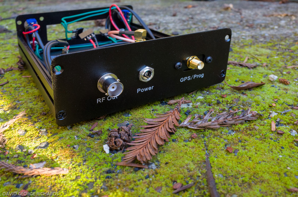
Tayda Electronics is now carrying a small range of enclosures, including some diecast ones, and they have great prices. I ordered a couple of sizes to see how they were, and ended up using the smaller one for this beacon. Here’s the board mounted inside it’s enclosure –

original16

That’s a small dummy load plugged into the BNC connector. Once connected, you can measure the peak to peak voltage across it with an oscilloscope, and use that to calculate the output power.

original17

original18

Although you can’t see them, I fixed 4 little vinyl bumpers to the bottom of the case.

original19

Once you have this little powerhouse in an enclosure, you’re ready to set the output power with the 2.2K drive trimpot. Ideally, you’d be able to accurately measure the field strength at 30 meters from the antenna and use that as your yardstick. This is what K6FRC did when setting up his “FRC” HiFER beacon. IIRC, he runs 1.8mW into a groundplane. I saw an online posting from him in which he said that he was running very close to the maximum permitted field strength at that power level (he has access to a field strength meter). As I don’t have an FS meter, I chose to go with the results from W1TAG’s paper and chose 4.6mW into a dipole as my goal.

If you have an oscilloscope with a bandwidth high enough to measure voltages at such frequencies, it is a useful tool for measuring the output power of your beacon. As the power is specified in terms of the field strength it generates, there is no need to locate the transmitter close to the antenna feedpoint in order to minimize losses. If the regulations specified a maximum power out of the transmitter final, then this would be a worthwhile approach. This is the case with some Part 15 allocations (such as the one for the MW AM broadcast band). However, in this band, we are free to calculate the loss of the feedline and adjust the transmitter power accordingly.  This means that the transmitter can be located indoors, and away from the extremes of weather and temperature.

With my MFJ-259B, I measured the loss of my 50 feet of RG8-X at about 0.7dB, and figured that a transmitter output power of 5.4mW should result in about 4.6mW at the antenna. Using this online calculator, 5.4mW translates into a peak-to-peak voltage of ~1.47V into 50 ohms. With the 3.3V regulator in circuit, the maximum power output was only 10mW,so adjusting the drive to produce 1.47V peak-to-peak on the scope was fairly easy.

Incidentally, the backwave is very audible when you are close to the transmitter. The backwave is the carrier that is still radiated from the antenna when the keying is off. This happens because we are keying the final, so that when the key is “up”, some of the signal from the oscillator still leaks through the PA and into the antenna. I measured the backwave on this transmitter as 01.mW, and it remains at the same level regardless of where the output power is set. Granted that at lower output levels, such as 5.4mW, it is a greater fraction of the power when the key is “down”, but although I could hear the backwave in my immediate neighborhood, it gets lost in band noise pretty quickly. 0.1mW is about 34dB lower than 5.4mW, meaning that if someone is hearing the beacon at S9 +30dB, then the backwave will be a little over S8. Realistically though, anyone who is not really close to it will not be hearing the mighty 4.6mW signal at anything more than a few meager S-points at most, relegating the backwave into the noise. If it really bothers you, you could run the transmitter from a 5V regulator, set the output power higher, and then reduce it with an attenuator pad in the output circuit. That would lead to less backwave in the antenna. I didn’t bother about it.

Here’s the antenna – a Buddipole vertical element, mounted on a painter’s pole on the balcony of my house, putting the base of the L-shaped dipole at aobut 25 feet above ground level. The other element of the dipole is a length of wire. It’s a pretty good take-off to the north and east, but it is blocked by the house to the west and south –

original20

This is what the beacon sounds like on the K2 in my shack. I purposely took steps to reduce the signal level into the receiver, so as to get an idea of what it would sound like at a distance –

Here’s Mingus the neighborhood cat, listening to the Sproutie beacon on my K2, from across the street. Apologies for the cat butt! You can hear the backwave in this video –

The “SPT” Sproutie Beacon is now sitting in my shack, pumping it’s plucky little signal into the ether 24/7, and has received 2 “DX” reports so far. The first was from Jeff KF7RPI, who heard it at his QTH in Portland, Oregon, briefly at a 239 – 339, before it faded back into the noise. He is about 530 miles from me as the crow flies, which is pretty good for such a QRPp signal. The second report was from Bill Hensel on the LWCA message board. He was hiking in Pike National Forest when he heard SPT one day at 1845utc (also briefly) on his KA1103 portable receiver. Bill was about 900 miles distant from me, so that is also exciting. These are the only 2 reports SPT has received so far, but it is encouraging. Some folk do run grabbers on this band and look for QRSS signals. I’m thinking that if SPT’s 4.6mW signal can be heard at 900 miles while at 6wpm, it could go a lot further if it were sending much slower. However, I do like being able to decode it with my own ears, so will keep it at 6wpm (or maybe 12 wpm) for the time being.

Incidentally, if you want to put a HiFER beacon on the air with the minimum of fuss, the Ultimate 3S QRSS/WSPR transmitter kit from QRP Labs will operate on any frequency in the HiFER band, thanks to it’s Si5351 frequency synthesizer. The LPF for 20M should work fine for attenuating harmonics. As this kit is capable of producing far more power than Part 15 regulations allow, it is your responsibility to limit the output power if you operate this transmitter on the HiFER band. The Ultimate 3S will do multiple modes and bands – it’s a do-it-all-in-one MEPT, really, and at a very affordable price.

original22

If you hear the SPT beacon on 133558KHz, please send a report – either to the e-mail address listed on my QRZ account, or as a comment underneath this post. Reception reports will be very eagerly received. One gentleman in Seminole County, FL, reported that the area around the SPT frequency was a cacophony of noise in his area, and he stood no chance of hearing it. Those kinds of reports are useful too.  If you put your own HiFER beacon  on the air, do introduce yourself on the LWCA message board, and John can include you on the list of known active HiFER beacons.

original21

4.6mW of legal, unlicensed pluckiness and grandeur, hiding out in a diecast box.


The Muppet-Style Construction of John N8RVE

$
0
0

I have been meaning to write a post featuring the inspiring construction work of John N8RVE for almost a year now but sadly, am only able to think about one thing at a time, and The Sproutie MK II took up a lot of space in my head last year. Then, after finishing that, my one-track mind switched off from home-brewing and blogging activities completely. I am still unable to contemplate any more construction projects, and think that I may have done everything I set out to do with home-brewing, at least for a while.

In the meantime, there are a couple of things I’ve been wanting you to know about, and one of them is the excellent approach that John takes with his projects. John and I first became acquainted when he built a Rugster direct conversion receiver, and a WBR. Then I saw his build of a broadcast band regen, and that classic QRP design, Dave Benson’s SW+40, and really started to take notice.

John uses a form of construction that has been championed by Chuck Adams K7QO, in his QRP-Tech group on Yahoo Groups. Chuck calls it Muppet Construction and it refers to the practice of using an etched PCB, but soldering the components directly to the copper traces, thereby negating the need to drill holes in the board for component leads. It makes the process of creating the board easier, as there are no holes to drill. Also, after the circuit has been constructed, it is easier to look at the component side of the board and figure out what is connected to what – a process that is much harder with conventional through-hole PCB’s.

Back in January of last year, John finished construction of a broadcast band regen receiver, based on a design by Rick Andersen KE3IJ. Here is his very nicely etched “Muppet” PCB –

original

BCB Regen Receiver (Photo courtesy of John N8RVE)

The board partway through construction –

original1

BCB Regen Receiver (Photo courtesy of John N8RVE)

And the completed regen (note the use of a rubber pinch wheel to achieve slow-motion tuning –

original2

BCB Regen Receiver (Photo courtesy of N8RVE)

John’s next project really caught my attention. It is the classic QRP design, Dave Benson’s SW40+. Dave has retired, and the SW40+ is no longer available as a kit (perhaps sometime in the future it will be again?) I’m sure there are many folk who would love to build a SW40+ but lament the lack of availability of a kit. Luckily, the kit manual, including schematic, is freely available online so the obvious answer is to build your own, which is exactly what John did. You could build it Ugly-style, Manhattan-style or, as John chose, Muppet-style. Here is his fully populated board –

original3

SW40+ (Photo courtesy of N8RVE)

Doesn’t this just look fantastic? This is very inspiring John!

original4

SW40+ (Photo courtesy of N8RVE)

Then, using the same technique, John built a HiMite 20. The HiMite 15 and 20 were next-generation QRP transceivers based on the Rockmites and, like the SW series of rigs, were the brainchild of Dave Benson. This is John’s version of the HiMite 20. When he first e-mailed me with news of this project, he was having some problems with the receiver. I’m not sure if he was able to solve the issues, but I think it looks great –

original5

HiMite 20 (Photo courtesy of N8RVE)

Just before his muppet construction odyssey began, John built a WBR, but ended up giving it to a friend who liked it. What to do? Build another one! This one is for the 31M broadcast band. John has had some issues with the volume level though otherwise, it is working OK –

original6

WBR Receiver (Photo courtesy of N8RVE)

One of the great things about developing the ability to scratch-build (as opposed to assembling projects from kits) is that you can pretty build anything you want, as long as you have the schematic. You can build it using any one of a number of techniques – Ugly Construction, Manhattan, Muppet, or any combination that you wish. You could even design your own PCB and take the drastic measure of drilling holes in it for component leads :-)

Thank you for sharing the details of some of your projects with us John, and I hope they inspire some readers the way they did me!


Georges F6DFZ’s Very Stylish Homebrew Version of The Scout Regen Receiver

$
0
0

Several months ago, Georges F6DFZ sent me pictures of a Manhattan project he had just completed, using Rex’s MeSQUARES, and I have waited far too long to share it with you. It began life as a copy of the Ten Tec 1253 regen, but George said that the results and usability were very poor. One thing that must be said about regens is that the ones which don’t work well are very dispiriting. However, when you come across a good design and build it well, the performance can be very satisfying indeed. Luckily, Georges didn’t let his initial regen experience put him off, and he ended up turning the project into a receiver based on the Kitchin-inspired Scout Regen. He normally uses PCB software to design custom boards for his projects, but decided to try Manhattan construction for this receiver.

I like how his project was obviously the result of considerable careful planning –

original7

Now this is what I call planning! (Photo courtesy of F6DFZ)

The slow motion drive came from a very old French military surplus rig. George says that it tunes very smoothly with no backlash, and has 2 ratios – 10:1 and 100:1. The operator pulls on the tuning knob to shift to the slow tuning rate –

original8

The ex-military slow motion drive and dial (Photo courtesy of F6DFZ)

The front end is taken from the Scout regen. Georges added an RF preamp stage. You can see the RF board and tuning capacitor in this photo. I am guessing that the polyvaricon is for fine tuning –

original9

Rear view of Georges’ regen receiver (Photo courtesy of F6DFZ)

A closer view of that RF board –

original10

Photo courtesy of F6DFZ

From above –

original11

Photo courtesy of F6DFZ

The AF stage in the Scout design uses an LM386 with the ubiquitous 10uF capacitor between pins 1 and 8 for a stage gain of 46dB. While offering high gain with a low component count (and a low quiescent current), this circuit configuration also introduces a lot of hiss. Georges used a more complex, and lower noise audio chain. A MAX293 device provides 8th order low-pass filtering for good audio selectivity, and feeds an LM380 AF output stage. Using a relatively low noise device such as the LM380 makes listening much more pleasant, in my experience. Both my Sproutie and Sproutie MK II regens use one, and I regularly listen to them both for hours at a time. Good filtering, such as the arrangement that Georges has used, also does a lot to reduce unnecessary static and noise that can make listening for long periods fatiguing. Here are the AF stages, located underneath the chassis –

original12

AF Stages underneath the chassis (Photo courtesy of F6DFZ)

Another view of the topside of the chassis –

original13

Photo courtesy of F6DFZ

Georges also added an S-meter, which he got from a QRP book by Doug DeMaw –

original14

Photo courtesy of F6DFZ

This receiver operates on 80M and 40M. The band coverage on each band is 3.48 – 4.8MHz, and 6.95 – 8.5MHz respectively. Everything was done with hand tools, and a sheet metal brake which was made from an article in QST – this was indeed an admirably home-brew project! It even has dial lights –

original15

A real dial – with lights! (Photo courtesy of F6DFZ)

I love how Georges fabricated his own custom chassis from sheet aluminum, and paid attention to all the mechanical aspects of the design, making sure to include a dial and slow motion drive. These are the aspects of making your own equipment that can be very time consuming but which ultimately, make the project more enjoyable to use, and helps to ensure that it will occupy pride of place in the shack for years to come.

Incidentally, Georges wrote an article that appeared in the Oct 2014 issue of QST, on a CW adapter for the Collins KWM-2A transceiver. You can view it here if you have an ARRL membership. Thank you very much to Georges for being willing to share these pictures and details of his wonderful regen. I find it very interesting to see how other people build their projects, and I know a lot of others do.


A Scratch-Build of N6KR and Wilderness Radio’s SST for 20M

$
0
0

Note – all links in this post open in a new browser window. It would be a good idea to clear your cache from time to time, to make sure your browser loads the latest version of this post. As an example, I just found an error on the schematic, and uploaded a newer, correct diagram.

I’ve been wanting to build an SST for a few years now. It’s a plucky little rig, with a lot of character. Designed by Wayne N6KR in the late 90’s, appearing as a full article in QRPp, and a kit sold by Wilderness Radio, it ignited the imaginations of a whole generation of builders for it’s combination of simplicity, performance, and willingness to accept modifications cheerfully. The review from Adventure Radio Society was quite positive. It is a VXO-based QRP CW transceiver, with a simple superhet receiver (SST = Simple Superhet Transceiver), and a TX that puts out up to 3W, depending on your choice of transistor in the final (it can be dialed down for battery-powered outings). It has very fast, clean QSK – so fast, in fact, that it feels as if I can hear the band all the time I’m sending (W6JL would approve). You actually listen to your own signal as you’re sending – there is no separately generated sidetone. The sidetone level does vary with the volume control, as opposed to being a fixed volume, but I only find this to be an issue when I have the AF gain all the way up, in which case I either quickly adjust the volume knob, or partially pull the earbuds away from my ears while sending. By the way, the sidetone on this little rig sounds really nice. It’s a feature which helps to make operating the SST an enjoyable experience.

QRP’ers loved their SST’s. There was a lively discussion about the minimalist rig on QRP-L, with builders reporting back on the frequency coverage and performance of their builds, with details of mods they were trying. The kit came with a light gauge unfinished aluminum enclosure. The raw-finish aluminum was a blank slate which invited many different creative solutions to the age-old question of how to show off your project. Some folk endowed theirs with professional-looking paint jobs, while others used dymo labels, or simply scrawled right onto the panel with a Sharpie® for that authentic home-brew look. All approaches worked admirably well. I saw one SST that had been painted with a US flag, and looked great. Some of them were taken out on the trail many times, and showed many knocks and scratches on the case which, of course, just made ’em look better still.

original

SST Kit Version – Image from Wilderness Radio

original1

SST Kit Version – Image from Wilderness Radio

JN3-bong;y modified his SST with 2 varacters for extra frequency coverage. He also added a speaker, and a spot button. Click on this photo to go to his site, and read more about his SST.

Koichi JN3DMJ modified his kit version of the SST40 with 2 varacters for extra frequency coverage. He also added a speaker, a spot button, and expanded the LPF for better filtering of the transmitted signal. Click on this photo to go to his site, and read more about his SST. He says that this SST is his favorite rig. He has made over 1300 QSO’s on it so far. Thank you for the permission to reproduce this photo and link to your site Koichi.

Recently, I decided it was time to build my own SST, only to find that I had missed the boat on a kit, as Wilderness Radio had discontinued it at some point in the recent past. I called QRP Bob on the phone, hoping that there would perhaps still be a board and/or enclosure available, but I was out of luck. In fact, it meant that I was in luck, as I would have to scratch-build one, and that’s a good thing.

There is plenty of documentation for this rig online. The initial write-up was in the Spring 1997 edition of QRPp, available from Chuck K7QO here. Note that the preceding link is a PDF of all 4 volumes from that year. The entire QRPp archive is also on Chuck’s site and accessible from the main page. Ken WA4MNT has a copy of the manual for the Wilderness SST kit on his site. Other essential documentation is the mods and information collected from QRP-L messages from 1997-2004, from Ken Larsen AL7FS, here as an HTML file, here as a text file, or here as a .doc file.

Mine differed just slightly from the original. Here’s my hand-drawn version of the schematic, reproduced here with kind permission of N6KR. Don’t rely just on the following schematic, as my drawing is a bit goofy. Best to refer to the original circuit diagram in the manual, and use mine to see how it differs –


Note – I do not recommend using the LPF comprised by C34, C35, C36, L2 and L3. Although it just met FCC specs at the time of release, it is very unlikely to provide enough filtering for this rig to meet current FCC rules regarding suppression of spurious emissions. For more satisfactory filtering, see my post here. 

Component designations (e.g. C27, R11 etc) are the same as in the schematic in the Wilderness Radio manual. There are 3 parts in the above schematic that do not have such designations – they were added by me (the series capacitor and resistor from pin 5 of U3 to ground, and the 1N5817 diode in series with the 10-16V DC supply line).

Differences between the stock SST and mine are –

1)  Inclusion of a series  diode in the supply line for polarity protection. I did consider using a P-channel MOSFET so as to avoid the voltage drop, but decided to go with a Schottky barrier diode. Some diodes of this type have a big enough reverse leakage current such that they are not effective in this role, but not so the 1N5817. It’s forward voltage drop is about 0.34V in transmit. I still don’t like losing that much, but it’s an improvement on the higher drop of a regular silicon diode.

2) The use of trimcaps in the RX and TX oscillators in order to place the received signal in the center of the passband, and to put the TX signal on the same frequency as the RX signal. I’m still about 20Hz off due, I think, to touchy trimcaps, but it’s close enough – until I get the urge to tweak and adjust again🙂

3) The use of 68pF capacitors for C19 and C20 instead of the 100pF values specified. With 100pF feedback caps, my VXO wouldn’t oscillate, so I swapped them for 68pF ones, and it sprang into life (thanks to LA3PNA for the help on that). It may well also have oscillated with 82pF caps, and that is an option if you want your frequency coverage to be a little lower.

4) An MRF237 was used for the final instead of a 2N3553. This substitution was suggested in the manual for higher output power, as the MRF237 has higher gain. If you want a cheaper and more modern alternative to the 2N3553, I’m thinking that a BD139 should work as a direct replacement. Joel KB6QVI just told me that W8DIZ has the 2SC5706 at 10 for $4, and I’m wondering how it would work in this application.

5) A Zobel network was added to the output of the LM386. Mine was unstable at high volume settings. A series capacitor and resistor from pin 5 to ground is very commonly used in these circuits, and the inclusion of these 2 parts tamed my instability immediately.

6) Alternate values of the capacitors in the crystal filter were used to widen out the response. The original values were reported to be giving a particularly narrow bandwidth of around 200 – 300Hz at the -6dB points. I wanted something a bit wider. There were several suggestions in the QRP-L archived discussions. K7SZ tried widening his SST20 out with the help of these suggestions, but it still wasn’t wide enough for him. He suggested the use of 47pF for C6 and C9, and 120pF for C7 and C8, which is what I used. Thanks Rich. A few builders went further, and implemented the ABX (adjustable bandwidth crystal filter) mod that was used in the Wilderness Radio version of the NorCal Sierra. EDIT – K7SZ notes in his ARRL book “Low Power Communication” that his mod brought the center frequency of the filter down too low for him on his SST30, so he ended up going back to the stock values. I have found that using the values of C7/C8 = 120pF and C6/C9 =  47pF that Rich suggested on QRP-L for his SST20, I set the sidetone at 400Hz ( a new thing of mine – I’m experimenting with lower than normal sidetone pitch), and the center of the filter passband was still about 20Hz lower, which I guess is pretty close. If you like higher sidetones though, you may be better off with one of the 2 sets of stock values in the SST manual. SECOND EDIT – I plan to tighten the response of the filter, by using the alternate values quoted in the manual. After using the SST for a while, I think my version is a little wide.

Although the SST didn’t come with a keyer, many users added their own, the Wilderness KC1 keyer and frequency readout being popular. At the time of writing, this is still available – the only kit that Wilderness still supplies. I decided that I wanted to build a keyer onto the same board as an integral part of my SST. I didn’t need much in the way of special features, my only 2 requirements of a keyer for this rig being that it will operate in iambic mode B, and that it has a speed pot – a feature I think of as essential. Changing speed on the fly during a QSO is tricky if the option is accessible only via menus, but a piece of cake if all you have to do is reach out and twist a knob. Perhaps I didn’t look hard enough, but the only freeware I found didn’t support a speed pot. I remembered how well the N0XAS Super PicoKeyer that Dar W9HZC had given me had worked, and a light went on in my head. Dale sells spare chips for his PicoKeyer Plus at $6 each. I purchased 4, used one in this rig, and saved the others for future projects. The manual on Dale’s site will give you the info on all the features of this keyer, and how to access them. The surrounding circuitry is simple (the genius is in the coding), so it was easy to incorporate into the SST –

The on-board keyer used a replacement PicoKeyer-Plus chip from Dale N0XAS

The on-board keyer used a replacement PicoKeyer-Plus chip from Dale N0XAS

The keyer uses a piezo transducer to announce the responses to command inputs made via the CMD pushbutton and the paddle. It would be possible to feed this audio into the AF amp of the SST so that it can be heard in the earphones, but I elected to fit a small piezo transducer on the edge of the board. I had intended to punch a small hole in the side of the case to make it easy to hear, but this appeared not to be necessary. Note that in the schematic, I have called it a piezo “buzzer”. It is actually a transducer, but allow me to explain. There are piezo buzzers available to which you apply a voltage, and the unit rewards you with a loud piercing tone, generated by an internal oscillator. Some of the units available are called piezo buzzers, but they don’t contain the audio oscillator – just a transducer, which is often sharply resonant at a specific audio frequency, to enhance the volume of the emitted tone. I bought a 5-pack of so-called “piezo buzzers” on eBay. They looked too small to contain an internal oscillator and I was correct – they consisted of just the transducer, which was exactly what was needed.

This build looked great when it started (as they all do🙂 ). A nice, clean board, with nothing but potential. As projects progress, I tend to become more anxious that in a single unconsidered moment during a late night soldering session, the iron will slip, the odor of burning plastic will waft into my nostrils, and all the hard work will be undone in a careless fraction of a second. In truth, there aren’t that many errors that can’t be corrected, but this early shot of the board was the best it ever looked! As with all my projects, all the Manhattan pads were MePADS (for IC’s) and MeSQUARES (for everything else) from Rex at QRPMe

If you compare the above photo to later pictures, you’ll notice that I ended up changing the layout of the front panel controls.

In the next picture, the AF amp and the VXO have been constructed, as well as the 8V regulated supply line. Temporary DC and headphone jacks were also connected, so the circuit can be plugged in to see if it works. The shielded cable that connects to the tuning pot was installed, but left longer than needed to allow for the final install in the enclosure. Not too much of the circuit had been built at this point, but it was already possible to test the voltages at the input and output of the regulator, as well as ensuring that the LM386 made a nice, loud noise when the input terminals were touched with a screwdriver (a highly controlled and accurate test🙂 ) The VXO was tuned in on a nearby receiver and tested for frequency coverage. With the 20M version, the VXO is in the 18MHz range, and by subtracting the IF of 3.932MHz from the highest and lowest frequencies it oscillates at, you can estimate the final coverage of the SST, and make adjustments at this stage if you wish. The discussions on QRP-L (which are linked earlier) contain a lot of info on tailoring the coverage, so I won’t repeat it all here, but your options involve using different varactors, connecting a second crystal in parallel with the VXO crystal, using different values of rubbering inductor, and adjusting the value of R5. I won’t explain how these all affect the frequency coverage and stability, as this is discussed at length in the QRP-L archive and also, to a certain extent, in the manual. There is plenty of homework reading to be done if you are thinking of building this rig!

Here’s another view, with the VXO in the foreground –

Suddenly, the product detector and BFO burst onto the scene. In the next shot, the 3.932MHz BFO crystal is the one closest to the camera, with the trimcap for centering the passband just behind it. I used 60pF trimmers, as that is what I had the greatest quantity of. Something a little smaller might have made the adjustment less touchy though. I’ll leave you to experiment, if you want to. Things are getting pretty exciting at this point, because when you a touch a wire or metal screwdriver screwdriver to pin 1 of the product detector IC U2, you hear honest-to-goodness atmospheric noise – a distinctly different sound from what you hear when touching the input of the AF amp IC. It’s instructive, not to mention really cool, to hear this progression in the sounds you hear, as you touch the inputs of stages closer and closer to the antenna, as the build progresses. If you have a signal generator, you can inject that into the circuit, and look at the output on a ‘scope. Don’t despair if you don’t have a full stable of test gear though – it’s important not to underestimate the power of touching and listening. Once you’ve done it a few times, you get used to knowing what sorts of things you should be hearing. See the curved red power wire that supplies 8V regulated to the BFO/product detector? You’ll notice in later photos that it was replaced with a different-shaped wire. It’s rarely possible to get everything right the first time you construct something, so one-off builds like this tend to morph somewhat as they progress. It’s OK to change things as you go along –

The next stage to construct was the crystal filter. Do you notice how, on the board for the kit version of the SST, the crystals for the filter were lined up with the short edges parallel to each other, so that the filter takes up a significant length of one side of the board? You usually see filters with the long edges of the crystals lined up parallel to each other. I don’t know why Wayne did it this way, but it did occur to me that with this physical configuration, the input and output of the filter are further apart than they would be with the more conventional placement pattern. Perhaps this was an attempt to decrease the possibility of filter blow-by? It seemed like a good idea, so I replicated it in my Manhattan copy. The crystals in the filter are not yet grounded in this next shot –

As far as matching the 3 crystals for the filter, I placed them into an oscillator circuit, and measured the frequency of oscillation. My cheap Chinese stand-alone frequency counter only had a resolution of 100Hz, but then I remembered that my K2 had a built-in counter with a 10Hz resolution, so I used that. I needed 5 x 3.932MHz crystals total – 3 for the filter, and the other 2 for the oscillators in the TX mixer and the BFO/product detector, so I picked the 5 that were closest in frequency. Out of that group of 5, I took the 3 closest and used them for the filter, while the other 2 were used for the local oscillators (but not the VXO, which required an 18MHz crystal).

To verify that the receiver is working, you’ll need to also build the antenna LPF, consisting of L1, L2, and associated parts. Without it, you won’t be able to peak the antenna input trimcap C1. Notice that if you touch the input of the crystal filter, the noise from the phones sounds much more restricted than when you touch the output of the filter. In fact, you can work your way back through the filter, with the rushing atmospheric noise becoming more and more restricted-sounding as you touch each stage of the filter with your metal screwdriver. These quick checks help to confirm that your project is pretty much on track. Adding the receive mixer means that the receiver is complete. After peaking C1 for maximum band noise, you should be able to receive off-air signals. Congratulations! If you substituted a trimcap for C10, you can also adjust it to place the received signal in the center of the passband, an adjustment that will depend on what pitch of sidetone you like to listen to.

My receiver didn’t work particularly well at first – I was getting very low audio out of it. One or two posts in the QRP-L archive made the same observation. I was beginning to talk myself into believing that the design was deficient in the audio department, and resolving to substitute a different audio chain, when I discovered that the coax which delivered the output of the VXO to the input of the RX mixer wasn’t properly soldered at the output of the VXO, resulting in low drive to the RX mixer. Re-soldering the joint solved the problem, and I can happily report that the audio output is more than adequate to drive a quality set of earbuds or a pair of reasonably sensitive headphones. If you attempt to drive a speaker, you will find that the level is only adequate for monitoring whether a frequency has activity or not, in a quiet room. That’s fine, as this was designed as a trail-friendly rig, with low current consumption in mind, and it certainly achieves that. VK3HN mentioned to me the idea of adding a lower noise AF chain designed to drive a speaker, and retaining the original AF output stage, feeding the inputs of both in parallel. The advantage of this would be that you’d retain the AGC action provided by the LED.

See the VXO in this next shot, with it’s 18MHz crystal? It has a total of just 10 parts, including the tuning potentiometer. I know that it represents old, well-established technology, but I feel that it still has it’s place in ham home-brew. Only 10 parts, and yet it has great stability and signal purity too. As long as you can deal with the fairly limited frequency range, a VXO is still a great choice as the frequency control in a simple rig –

This is always the point, when building a transceiver, where I slow down and spend some time playing with the receiver. I was dead chuffed, as we Brits say, that I had successfully built a little superhet receiver with a narrow crystal filter, that was sensitive, and sounded good.

But at some point, the momentum needs to be capitalized on before it is all gone, and so the build proceeded, with the addition of the transmit mixer. I also added the keying line (the green wires around the edge of the board) so that I could key the TX to see if it worked. If it did, then all that would be required would be to amplify the output of the TX mixer with the driver/buffer, and the PA. We were really getting close at this point! You’ll notice that there is a “channel” of space separating the crystal filter from the rest of the circuit. I did this for two reasons – firstly, as I thought it couldn’t hurt to physically separate the filter a little, to help prevent filter blow-by. Secondly, if there was excessive blow-by, it would give me enough space to erect a screen made from PCB material. C39, the 470uF AGC capacitor, is not present in this shot, nor in the later overhead notated view. I was planning on mounting it off the board, on the inside front panel, but eventually decided to mount it on the board. It ended up occupying the space between the AF amp and the edge of the board –

If you look carefully at these pictures, you may notice one or two components changing position slightly. As the build progresses, I will occasionally move a part or two in order to refine and improve the layout. I’m not going to point out which parts this applies to, as I don’t show these photos with the intention that you follow the layout closely. I started out by following the layout of the stages on the board from the SST manual but as the build progressed, realized I’d be able to move the position of the driver/buffer, thereby freeing up space for the on-board keyer, in one of the back corners of the board. Here’s another view of the board in the same state as in the above photo, with the receiver fully built, as well as the TX mixer. If you have a scope, you can measure the output of the VXO, which should be between 200 and 500mV RMS (that’s 0.565 – 1.414V peak – peak). You can also adjust C28 to peak the signal that will drive the buffer –

This was really the point at which I felt that I was home free. The TX/RX switching was working well, and the rig was putting out a small signal on the operating frequency in the 20M band. All that was left was to amplify it – and even if that didn’t work, I still had a cool little receiver and let’s face it – receivers are cooler than transmitters🙂

The next shot shows the rig fully built, with the exception of the keyer, with the board temporarily mounted in an enclosure. I ended up changing the layout of the front panel controls, which necessitated the use of another enclosure. In both cases, I used the LMB Heeger 143 enclosure in plain aluminum finish (they also have it in black and grey). I used an MRF237 instead of the 2N3553 in the PA, in order to provide a bit more output, and you can see that transistor, wearing it’s heatsink. To the right of the PA transistor is the orange top of R12, the drive control, and to the right of that is the LT1252 driver/buffer stage. The RF input to the LT1252 is carried by a single wire underneath the board. There are only 2 wires under the board – the one just mentioned, and a length of RG174 coax connecting the output of the VXO to the input of the RX mixer –

A view of the completed board, with the N0XAS keyer in the rear left-hand corner (which is actually the rear right-hand corner, if you are looking at the board from the front panel end). I mounted the keyer chip in a machined socket. I run as many of the control cables as possible underneath, and drill holes in the board for them to enter. I think it looks neater that way –

This next view shows the layout. I got carried away and labeled a few too many parts. The side of the board that faces the front panel is the left edge. As with the previous overhead anotated view, C39, the AGC capacitor, is not shown here, though it did end up being mounted on the board. Remember those SMD SA602’s I was giving away for the price of postage a while back (courtesy of KV7L)? I hadn’t used any myself, until now. 3 of them are in this little rig –

Time to get this thing in a case. The LMB Heeger 143 is an ongoing favorite of mine. It measures 4″ x 4″ x 2″ high, and has 2 small lugs at the front and back of the cover that engage with the front and back panels to prevent them from being pushed in. This feature adds rigidity and stoutness. One of the things I don’t like about most clamshell cases is that the front and back panels can be flexed; not so with this model. It comes in grey and a sort of black wrinkle finish, if you don’t want the raw aluminum. All the pots are Alpha brand. The 3 small ones were $1.29 each from Tayda. The larger tuning pot is also an Alpha part, but is very slightly smoother in action, and I wanted to optimize the experience of tuning this rig. It is Alpha part # RV16AF-10-20R1-B10K-LA (I got it from Mouser).  There is a small dummy load plugged into the back in this next shot, because I was having fun using the rig as a code practice oscillator🙂

This SST is quite a triumph for me, as it is the most complex project I have built so far with Rex’s MeSQUARES and MePADS.

The piezo transducer for the keyer was fixed to the edge of the board with a small spot of hot glue (on the high temperature setting of the hot glue gun, as it flows better) –

The keyer CMD pushbutton was a 22 cent cheapie from Tayda. These types are available with plastic and metal shafts. The ones with the metal shafts have a slightly smoother, more positive action. Get those ones. 4 vinyl bumpers from the local hardware store keep the SST from slip-sliding on my desk –

This enclosure is higher than the kit version, at 2″ high. I wasn’t initially planning on such a high case but the advantages are that it supports a larger tuning knob and, as you can see from the next shot, there is room for an internal battery pack, speaker, ATU or other add-on –

Here’s a view of the SST-20 upside-down and from the rear. From left to right – RF gain (rarely used), Antenna, DC power, and paddle –

I have a couple of spare covers for this enclosure, from projects that didn’t go as planned, and am thinking that it would be possible to have different covers with different accessories built in. For instance, one cover could have a speaker and extra AF amplifier, for operation at home. Another cover could contain a battery pack, for portable ops –

The red and yellow knobs look a bit garish, and I’m still getting used to them, but the thinking is that yellow = audio (AF gain and headphones), while red = keyer (speed pot and CMD button). It was also a way of using the cheap knobs I got from Tayda for 49¢ each🙂

So how does it perform? Well, in 2 words – very well. I don’t operate a lot, but I do spend a lot of time listening. I’ve had 6 QSO’s so far with a horizontal loaded dipole (a Buddipole) at 25 feet above ground at my home QTH. 3 of them were with stations in Colorado, about 900 miles distant, one with KE5AKL who was doing a SOTA activation in NM, also 900 miles from me, and one with a mobile station in Hooks, Texas, who was running 25W. He was 1600 miles away as the crow flies. The other was with a local station. The receiver is as sensitive as you’d need a receiver to be, and there’s a good amount of opposite sideband suppression. I haven’t measured it, but you only hear the opposite side of the signal weakly when tuning through a very strong station. The RF gain only needs to be backed down when in the presence of very strong stations, as the use of an SA602 in the front end can cause it to crumble under such circumstances. I haven’t needed to use it yet, and from what I’ve read, it doesn’t need to be used very often – hence the reason it is on the back panel. My frequency coverage, with an MV209 varacter, is approximately 14055 – 14064KHz, a swing of 9KHz, which is about as much as you’d want when tuning with a 1-turn pot. Many users mounted a switch on the front panel to switch in another varacter (usually an MVAM108, which was also supplied with the kit) to extend the coverage downwards. With the MRF237 in the final, my WM-2 wattmeter indicates an output power of about 2.25W with 11.61V at the input to the rig (11.27V after the polarity protection diode). When supplied with 13.8V from a PSU, the power output was about 2.8W. I didn’t measure the current consumption on transmit, but on receive it is between 26 and 27mA. This is low, but somewhat higher than the 15-16mA quoted in the manual. The keyer consumes <1mA, so that isn’t the reason for the difference.

The AGC LED is a rather unique feature. I’ll let you read up about it in the manual but for the addition of a few extra parts, it will save your ears from the worst ravages of sudden loud signals – and the LED is fun to watch too🙂 Most red LED’s have a forward voltage drop of about 1.7 – 1.8V. If you want to raise the AGC threshold, look for a red LED with a higher Vf – some of them go as high as 2.2V.

Although all the parts for this little rig are still available, a few of them are a bit harder to find than others. I purchased the LT1252 from Digi-Key – they have them in both through-hole and SMD versions. Chuck K7QO tipped me off to a supplier on eBay who was selling them in 10 packs. I couldn’t resist purchasing a pack. Thanks Chuck🙂 W8DIZ has the MPN3700 PIN diodes, though see the next paragraph for a worthy substitute.  There are several different choices for the PA transistor. 2N3553’s and MRF237’s were available on eBay when I was looking. Try to buy legitimate parts from a reputable supplier (my gut feelings seem to serve me well in this regard). I’m thinking that a BD139 would work in this position too. All the crystals are still available from Digi-Key. The part numbers are the same as in the SST manual, with the exception of X1-X5 for the 30M version. The manual quotes the Digi-Key part # as X007-ND. It is, in fact, CTX007-ND. Perhaps it changed. It has, after all, been 19 years since the kit was introduced!

Even though this design is now quite old, I think it is still very relevant. An experienced home-brewer can build this into a fairly small case, and take it on the trail with a simple tuner and, say, an EFHW, for a compact and effective portable set-up. All of the parts are still available, though it would be great to see a partial redesign, utilizing more modern and widely available parts. I’m thinking of a redesign of the buffer/driver and PA stages. BS170’s are cheap, and 3 of them in parallel, in class E, could provide close to the full QRP gallon. The original SST had room in the case for a 9V lithium battery, and could be dialed down to lower output powers to help battery life. Nowadays, newer battery technologies make more power available in a light and small package, so running 4 or 5W while portable with a small rig like this is practical. Kenjia JH1PJL used an NPN transistor in his driver, instead of the LT1252 IC. He also used a 1N4004 instead of the MPN3700 PIN diode (you can see pictures of his SST scratch-build here). In fact, all the diodes in the 1N4001 – 1N4007 series have the relatively slow recovery time of 30µS, giving them PIN characteristics. Any of them should work fine in place of the MPN3700. If a 1N4000-series diode is good enough for RF switching in the Elecraft K2 (the 1N4007), then it’s good enough for us!

Here’s a brief video of it in action, with a surprise appearance by Jingles the blind kitty. I fed her just before starting the video and forgot that her routine after eating, is to jump up on the desk to relax and digest her meal for a few minutes. I’ll work on producing a slightly better video, though videos are not my strong point. Apologies for the slightly crackly audio. It’s a combination of operator error and a camera that was designed primarily for stills, and not video –

The yellow knob was making me uncomfortable. It has since been replaced with a black one, and I am feeling much calmer now🙂

10 minutes later, and the red knob has now been changed for a solid and dependable black knob also. I finally feel that I know where I am in the world again🙂

For the near future, the next tasks are to –
a) add an extra stage to the LPF between the antenna and the rig for greater harmonic suppression and
b) tighten up the crystal filter a bit. I have decided that it’s just a little too wide🙂


A Single Lever Paddle From QRP Guys

$
0
0

When building the SST for 20M, my plan was to kit it out with a paddle, battery, and an easily deployable antenna, and head for the hills. That’s still the plan. I don’t operate portable very often, preferring the comfort of the operating position in my small apartment, where I can make as many drinks and snacks as I want, and do it all with the company of my 3 kitties. Bliss! However, having just made a small, lightweight CW rig, I have to take it out in the field at least once in order to prove it’s mettle.

Currently, the only paddle I have is a Bencher, which is a bit too heavy and cumbersome to carry in my backpack for a portable set-up. There are some really neat portable paddles on the market, but I didn’t want to spend much, so settled on the idea of making one from PCB material, inspired by Wayne NB6M’s paddle, and KI6SN’s version, which was based on Wayne’s design. Two things happened to stop that idea in it’s tracks though. The first was that, nearing the end of building my SST, I was beginning to feel a bit lazy. Occasionally, when wading my way through a scratch-built project, I ponder how nice it would be to build a kit and give my brain a rest. At around the same time, I came across the website for The QRP Guys and realized I’d hit paydirt. They have a selection of small and low-priced kits for the QRP’er, including some small paddles made from PC board for very affordable prices. Perfect! The QRP Guys are Chuck Adams K7QO, Doug Hendricks KI6DS, Ken LoCasale WA4MNT, John Steven K5JS, and Dan Tayloe N7VE. Holy moly – that is some serious QRP starpower. I think we’d all be well advised to keep an eye on what these guys are up to.

QRP Guys ship out once a week on Wednesdays. With any small ham business such as this, where the owner/operators have many other things going on, setting expectations is an excellent idea. I decided on a single-lever paddle, and ordered it over the weekend. Later in the week, a small bag of parts arrived in the mail –

QRP Guys provide a scale for you to gauge how easy or difficult each of their kits is to build. On a scale of 1 to 5, with 5 being the most difficult, this paddle kit is rated as a 4. They do mention that some kits may also be rated as requiring what they term “expanded skills” – meaning, I assume, more difficult than 5. The rating of 4 for this kit makes sense. The PCB paddle parts need to be positioned fairly accurately. The way to do it is with a light tack solder in one point, re-adjusting until the exact positioning is reached, at which point you can commit with fully soldered joints. There are quite a few small screws, washers, and other small parts, so care, and a container to put all the small parts in are good ideas.

Here’s the final paddle. What a neat-looking little assembly –

A view of the underside –

This paddle is intended to be fixed to a panel, such as the side of a portable transceiver. I wanted it to be on a base, so decided to fabricate one from single-sided PCB material –

The cable is a cord from an old set of earbuds that came to an early end in the washing machine. It has a small molded 3.5mm stereo jack on one end, which is perfect for the task. It is held to the paddle base with a loop of twisted wire that threads through 2 holes in the base. At the point where it is secured, the cable was covered with 2 layers of shrink tubing. Luckily, the flexible wires in the earbud cord were insulated with heat-strippable enamel, so all that was necessary to remove the insulation was a generous gob of solder on the tip of the iron, and a few seconds, for the enamel to burn off –

You can’t see them, but there are 4 stick-on vinyl bumpers on the underside, purchased from the local Ace hardware store – the same type I used on the SST –

The copper is not lacquered, so if I take the same photo in a few months, it won’t look quite as shiny –

For size comparison, here’s the paddle with the SST20 and a pack of playing cards –

Despite the little stick-on feet under the base, I’ve found that the most comfortable way to send with this paddle is to hold it in my hand. This will work well for portable ops, when a suitable surface on which to place it might not be available. The lever is made from springy stainless steel. Doug Hendricks reminded me of an old tip for finding suitable flexible metal strips for making your own paddle, if you wish to do so. Just visit your local auto parts store and purchase a feeler gauge – the tool that is used for measuring spark plug gaps. It contains multiple flexible metal strips, of varying thicknesses (and degrees of springiness), so you can pick the exact one to suit your preference.

I experienced a small learning curve with this paddle. Firstly, I had never used a single lever paddle and secondly, I wasn’t used to the springiness of the lever, as most keys and paddles use stiff metal for the pivoting part. It doesn’t take long to get used to though. If you’re looking for a cheap and rugged paddle, this is a good value for the money. QRP Guys have both single lever and iambic paddles, with and without a base.


Greater Harmonic Suppression and a Narrower RX Filter for the SST20

$
0
0

My scratch-build of the Wilderness Radio SST20 has been a great success. I’m not a very active operator but I’ve had 18 QSO’s on it so far, running it into a horizontal loaded dipole (a Buddipole) at 25 feet. The furthest was Hawaii at about 2350 miles distant, followed closely by Midland, PA at about 2200 miles away, as the crow flies. I previously thought the output power was 2.25W, but it looks as if it’s closer to 1.5W. I’ll explain why in this post.

Ever since completing it, I had been having uncertainties about the low-pass filter on the output. I understand that spurious emission requirements had used to be a little more lax for QRP transmitters, specifying that for transmitters under 5W, spurious emissions needed to be greater than 30dB below the level of the fundamental emission. This is no longer the case, as the requirement is the same for all HF transmitters in the amateur service, and is found in 97.307 –

“(d) For transmitters installed after January 1, 2003, the mean power of any spurious emission from a station transmitter or external RF power amplifier transmitting on a frequency below 30 MHz must be at least 43 dB below the mean power of the fundamental emission.”

Although I am not set up to make spectrum measurements on transmitters, a very rough test using the S-meter of my K2 indicated that my SST was emitting a 2nd harmonic that, at best, was only a few S-points below that of the main signal, It looked very much as if I wasn’t even fulfilling the older requirement of a minimum of 30dB suppression of spurious emissions. Digging around on the internet a bit, I found this paper on the GQRP site, giving practical values for low-pass filters for 50 ohm systems for all the HF amateur bands that I thought should satisfy current requirements. The suggested LPF for 20M was this –

As well as greatly improving harmonic suppression over the original SST filter, the use of this LPF in the receive path also improves image rejection as the image, with this receiver, is on the high side of the VXO.


Fitting it into the same space that the previous 2-stage LPF had occupied was a tough call, but I managed it. I did have to break one of my own rules of decorum, and allow one of the toroids to be slanted slightly, so that the layout looked less uniform (Oh, the horror!) but I was happy that it fitted into the space at all. The yellow T37-6 toroids of the new LPF are easily visible in this close-up view –

The first thing I noticed was that despite careful peaking of C28 (at the output of the TX mixer), the output power as measured on my OHR WM-2 wattmeter was now only 1.5W. Given that the 28MHz harmonic was previously very possibly only 2 or 3 S-units down on the main emission, I’m thinking that a significant portion of the 2.25W I was measuring at the output before was 2nd harmonic energy (and perhaps some unwanted TX mixer products too). The good news was that listening to the 28MHz 2nd harmonic on my K2 now revealed it to not even register S1, when the fundamental at 14Mhz was S9 +40dB! That is an excellent result, and one that falls well within FCC requirements. I observed a very similar result with the VXO signal at 18MHz. My K2 doesn’t cover the unwanted TX mixer product frequency of 21.932MHz (VXO freq + 3.932) – at least not with full sensitivity, and I don’t have a general coverage receiver with an S-meter unfortunately, so I can’t check the level of that unwanted emission.

The levels of the harmonics emitted from the antenna jack now easily comply with FCC Part 97. Due to the previous harmonic level I measured, I’m thinking that a significant level of 2nd harmonic is being delivered to the input of the PA and being amplified, before then being attenuated by the LPF. It would be preferable for that harmonic to be filtered out before the PA stage, and I may take a look at doing this in the future. In his SST40, JN3DMJ added an extra stage to the bandpass filter after the TX mixer to increase the level of spurious attenuation. You can see it here, under the heading “Upgrading of the filters”. With a better BPF in place, it may be possible to get an honest 2 – 2.5W from the final, with all of that power consisting of 14MHz energy.

As if to confirm to me that all was well, the little rig gave me a brief daytime QSO with KD3CA in Midland, PA – 2200 miles away. Not bad for 1.5W into a detuned dipole with an SWR of nearly 6:1!

The other thing that I took a look at was the crystal filter on the receiver. I had used the values of C6, C7, C8 and C9 suggested by Rich K7SZ on QRP-L for a wider response than even the values given in the manual for a wider filter. The stock values give a particularly narrow filter, and not all users will want that. I changed the values to those given in the manual as a mod for greater width. Does the way I’m explaining it make sense? I was going from extra wide to moderately wide, so to speak. Here are AF response curves taken by measuring the AF response of the entire rig at the headphone jack. The program used was Spectrogram.

Using K7SZ’ “extra wide” values of C6, C9 = 47pF, and C7, C8 = 120pF (the red vertical marker is at 400Hz – the sidetone I use) –

and using the “stock mod values” from the manual, for “regular wide response” – C6,C9 = 68pF and C7,C8 = 180pF (the red line represents an aggregate of all the peak values taken over a 16 second period, while the blue line is a response in one instant in time) –

Not sure if I’ll decide to go narrower with the filter, or leave it as it is. I need to experience a few more contest weekends before making any further decisions🙂

On an entirely different tack, I have been using a new camera for the one photo in this post, and all the photos in the previous post about my SST build. It’s much lighter, and more compact than the camera I used for the photos in all the other posts on this blog. I’m still trying to decide whether the image quality is up to par for me. It’s a different lens, with a slightly wider focal length, a different sensor, and I’m using different software to process the images. I am not quite yet used to using this particular lens in order to “see” my subject the way I want, and so there are a lot of factors in deciding whether it’s going to cut the mustard for use in this blog. However, it’s a great and relatively inconspicuous camera for carrying around with me. Occasionally, I like to do what one might call street and candid photography, and it excels at that. This is one of the things I do when I’m not slaving over a hot soldering iron –

But, for the most part, I prefer taking photos of radios. They are very relaxed and compliant subjects, and don’t give me a hard time when I point a camera at them, unlike some members of the general public (gee, I wonder why they would do that).

I’ll get back on topic and talk about radio in the next post, I promise. In the meantime, as I am getting the “neither here nor there” figure of 1.5W of power out of my SST20, I turned the drive down to 1W, to make it a nice, even figure. I am looking forward to sending “PWR 1W” during QSO’s!


An End Fed Halfwave Antenna for Portable Ops

$
0
0

I’m a very casual operator, and an even more casual portable operator. My main reason for not putting much effort into portable operation is that when I go out into nature, I want to enjoy my surroundings and not be distracted by radios. It sounds like an excuse, but it’s true. I spend quite a lot of time hunched over the bench and over my radios at home so when I go out, I don’t want to do the same. I’m more the kind of guy who builds small rigs, then operates them from the comfort of my own home. However, I had to take the SST out at least once simply to prove that I can!

The antenna needed to be compact and lightweight, as did the method of matching it. I just didn’t feel like carrying lots of boxes and interconnecting cables up the hill, and having to fiddle with them all once up there. An end-fed halfwave, often referred to by the acronym EFHW, seemed to be a good choice, as it only requires a support at the far end. I saw photos that Steve WG0AT had posted on Facebook of his little EFHW, with the matching unit built into a dental floss container, for a light and compact solution. I wanted an antenna that small and lightweight! Steve referenced a blog post by TJ W0EA, in which TJ detailed an EFHW matching unit he had made, based on the one in his Par End Fedz antenna. This little matching unit, that transforms the high impedance present at the end of a half-wave length of wire into the much lower impedance of 50 ohm coax, consists of a wideband transformer wound on a ferrite core, and a 150pF fixed capacitor. That’s it. Simple and compact!

What to put it in, was the big question. I spent several weeks looking in stores for suitable small containers, and finally decided on a Carmex lip-balm tube. Here it is with the lip-balm removed –

The remaining tube still has a corkscrew-like central element that needs removing –

It is a fairly simple matter to grasp  the corkscrew with a pair of long and slim needle-nose pliers, and push it until it pops out. You can discard the corkscrew, as it is not needed. The 2 parts on the left of the next picture, the snap-on lid and the main cylinder, are what you want –

The following pictures should show you how it all goes together. A plastic cable tie prevents the RG174 from pulling out of the bottom, and a generous squodge of hot glue keeps the toroid in check. If you have a dual temperature glue gun, use the hotter setting –

This matching unit is designed to work with a half-wavelength wire. Some folk build it so that they can change the wire length for different bands. I decided to make this a permanent 20M antenna, so started with about 36 feet, and continued to trim it down until the center frequency was close to 14060, at which point the SWR was 1.1:1. Not bad! I’ll state the obvious by reminding you that any antenna does need to be reasonably clear of nearby objects, particularly anything conductive, in order to make meaningful measurements. Laying it on the ground isn’t going to cut it – you need to suspend one end up in the air and have the antenna clear of obstructions. This is what my final EFHW looked like, all bundled up and ready for the trail, with a 10 foot length of RG174 –

Interestingly, a few days later, I checked the SWR again, only to find that although the center frequency was the same, the SWR at that point was higher, at about 1.4:1. The only thing that had changed was that the first time I measured the SWR, I was powering my MFJ SWR Analyzer from a “wall wart” transformer while the second time, it was powered from internal batteries. I’m thinking that the first time around, the AC wiring in the house was providing a bigger counterpoise and helping to lower the SWR at resonance. It might be interesting to try connecting a counterpoise wire at the rig to see if it reduces SWR any, but I did like the added simplicity of no counterpoise.

How does it work? I bundled the SST, antenna, small sealed lead acid battery, paddle from QRP Guys, and a few other things into my backpack, and cycled up to Vollmer Peak, a local high spot in the Berkeley Hills. I left rather late, had lunch on the way, and by the time I got up to the top, spent about 30 minutes eating trail mix and looking at the view, before realizing that I didn’t have much time. I didn’t get the antenna very high in the tree, and sat on the ground, listening, finishing off the trail mix, and putting out a few CQ’s before heading back down the hill. End result = no QSO’s, but I did get spots on the Reverse Beacon Network from Colorado, Arizona, and Alberta. The antenna works – it’s the operator who performs better in a cozy indoor shack🙂

There is really only one more thing to try with my SST, and that is, as I mentioned in this post, to add extra filtering between the TX mixer and the buffer/driver. I think that a lot of harmonic energy is making it to the final and being amplified, before being filtered out by the LPF in the antenna lead. Better to nip all those naughty harmonics earlier in the process, I think. If I do any more work on it, that will be the focus.

Thanks to Ian MW0IAN (great callsign) for clueing me in to this PDF on the G0KYA EFHW.


A WBR Regen On The 30M Amateur Band

$
0
0

Occasionally, I drag out old projects from their resting and display positions on my shelf, plug ’em in, and give ’em a whirl. It’s fun to watch as past home-brew rigs come back to life, and relive the feelings of wonder, as a handful of parts that I soldered together actually receive signals and in some cases, transmit them too. For me, the most wondrous times in building are those initial moments when a new receiver begins to pluck signals out of thin air. Those times of wonderment are often stretched out over a period of time, as a new receiver build progresses. I usually start with the AF stage of a receiver, and build backwards. The moment when I touch the input of the AF amp, and hear a mixture of hum and a general cacophony of broadcast stations isn’t so much a moment of wonder, as one of satisfaction that I can put that stage behind me and get on with building the real part of the receiver. Wherever the point is when RF is being converted to AF, and you’re hearing general atmospheric noise, it’s a magic time for me. It only gets better as subsequent stages are added, and the receiver begins to hone in on a very specific part of the RF spectrum. Mind you, there is something quite wonderful about hearing general atmospheric noise – it feels like an audio window into a wider world around us. I love that!

This is a preamble to the resurrection of the WBR that I built for the 31M broadcast band. Although I was initially happy with it, over time, I had to admit to myself that it seemed a bit deaf. Why was that? The original WBR that I built for the 40M amateur band was sensitive enough. Then I remembered that on the few occasions I had used to it to listen to 41M SW broadcast stations, it had also seemed a bit deaf. Perhaps it was just something about this design that doesn’t do well on AM? With that in mind, I decided to see how my 31M WBR performed on the 30M amateur band.

The existing receiver was already covering 9400 – 10000KHz, and a gentle adjustment of the trimcap in the tank circuit raised the frequency so that it was covering the 10100 – 10150KHz amateur band. The only other adjustment to be made was to limit the coverage to the 50KHz width of the amateur band, as it had previously been set up for the much wider 31M broadcast band. This can be accomplished by adjusting the range of voltages that are applied to the varactor diode, which usually involves nothing more complex than a judiciously placed resistor or two. I placed a 68K resistor between the bottom of the tuning pot and the trimpot, and changed the value of the trimpot from 5K to 10K –

The trimpot is used to set the lower edge of the band coverage, and the 10K value didn’t give me much adjustment range. I managed to get things set the way I wanted them, but suggest the values in parentheses, of 56K for the fixed resistor and 22K for the trimpot, as ones that would give more room for adjustment. If you’re building this from scratch, it might be worth looking into the use of 1N4001’s for the varactors. They’re cheaper and more widely available, and although they don’t give as wide a capacitance range as most varactor diodes, not much is needed when you just want to cover a 50KHz-wide band. You’ll probably need different values for the fixed resistor (if you even need a fixed resistor) and the trimpot. I’d start with no fixed resistor, a 5K trimpot, and go from there, if you do decide to experiment with a different part for the tuning diode.

The resulting receiver works well on the 30M band, with good sensitivity. Indeed, sensitivity is rarely an issue with regens – their main weaknesses are poor strong signal handling, and lack of selectivity. I have not yet heard a signal on my K2 that I couldn’t also copy on the WBR. This confirms my growing suspicion that this design just doesn’t cut it for AM, though it performs well on SSB/CW.

Another feature of this particular WBR version is the circuit of the LM386 AF amp, which provides enough gain to easily drive a speaker, and seems to have less noise than other high-gain configurations of this chip. I’ve heard from folk who built the WBR as described in the original QST article, and have been told that it has low audio. If you’re going to use that circuit, I strongly recommend that you include a preamp stage, as detailed in this post. Even better would be to use the circuit of the 31M WBR which, as well as including a preamp, also has the higher gain and lower noise LM386 amp stage.

If you’re into experimenting, Joel KB6QVI just bought some MD8002A audio chips from eBay. He reports that they have high gain (just like the LM386 in it’s souped-up circuit configurations) but, unlike that chip, is low noise. Like the LM386, it is intended for battery operation, so has low quiescent current. I’m thinking this chip could be a great substitute (not direct pin-for-pin though) for the 386 in many of our favorite well-known simple ham projects. Just a thought🙂

I’m really happy with how the WBR performs on 30M. It would make a neat receiver for a simple QRP transmitter running from a 10.106MHz crystal. Here are 3 videos. The first one is probably more informative, though the third one includes 2 of my cats🙂 I do tend to say some of the same things in all the videos, so apologies for the repetition, though I keep it more brief in the first one. If you’re only going to watch one video, watch this first one –

There was a lot of local noise during the recording of this next video. On top of that, I had not set the regen control properly. The set was well into oscillation, making it sound “hissier” than necessary. It also broadens out the response somewhat –

Once again, with this video, I had the regen control set too far into oscillation, widening the response and creating a bit more hiss than necessary. Really, if you’ve watched the other two, the only reason to watch this one is if you want to see some kitty action (2 of my gals feature in this one, beginning at around the 2 minute mark –

That’s the WBR on 30M, and I’m really happy with how it performs there.


Comparing the Weak Signal Performance of a WBR Regen with a K2

$
0
0

The WBR seems to get a bit of a bad rap with some people for it’s sensitivity. A comment on the last post from a reader called Simon, reminded me that some WBR builders have experienced poor sensitivity. Based on my experience, this design does seem to be fairly deaf on AM, but the sensitivity on SSB/CW is fine. I think there are two reasons why some builders experience low sensitivity –

1) They follow the schematic from the original QST article, and do not include an audio pre-amp immediately before the LM386. In this case, the receiver is not necessarily insensitive – it’s just that the low audio is limiting what you can hear.

2) The value of Z1, the inductance between the coil tap and ground, is not high enough. In the original WBR design by N1BYT, this inductance was a 1-inch length of #20 solid copper wire. I followed this direction with my first WBR (for 40M) and it worked well. The WBR was tackled as a group build in the QRP-tech Yahoo Group, as I have mentioned in this blog before, and some builders experienced low sensitivity. The fix was to replace the 1-inch length of wire with an inductor wound on a toroid. Builders in the group found the optimum value of inductance to be somewhere between about 0.2uH and 1uH. I went lower with my 30M WBR, and found that a value of 0.03uH  (3 turns on a T37-6) worked well.

Of the above 2 reasons, my suspicion is that 1) is the main one for most builders.

We regen fans do get a bit braggy about the performance of our sets. I could never make the claim that my regens perform as well as a superhet, for several reasons. Obviously, the strong signal handling of regens is pretty poor, and the bandwidth is wide. When a regen is adjusted close to the point of oscillation, the nose of the response curve becomes quite narrow, but the skirts are still broad. Also, it’s a small difference, but the fact that a regen listening to SSB or CW hears on both sides of the oscillator, as opposed to a superhet, which only hears on one side of the LO, gives the regen an immediate 3dB disadvantage. Basically, for a given signal, a regen is listening to twice as much bandwidth as it needs to (a doubling of power is an increase of 3dB). It’s not a big difference, but it is there.

Having said all that, I am constantly surprised by how much my regens do hear. I remember one evening, a few years ago, when the Russian K beacon was coming through very, very weakly on 7039.3KHz on my K2. I was amazed to discover that I could also hear it on my WBR. Admittedly, I had to strain to copy it on the WBR, and the fact that it was sending the same letter over and over again – and I knew in advance which letter it was, all helped. However, the fact that it was marginal copy on the K2, combined with the fact that I could copy it at all on my WBR (albeit even more marginally) was an eye-opener.

With all that in mind, here’s a 3 minute video of my K2 and 30M WBR side by side, both tuned to the same weak signal, as I swap the same antenna between both receivers. Hope you enjoy it. PS – no cats in this one!


Some New Tools and Construction Aids

$
0
0

I’ve added a few new tools and construction aids to the shack here recently and would like to pass the info on to you, in case it is of any help. The first is nothing out of the ordinary, but I’ll include it here, if for no other reason than the excellent instructions that were included. Daiso Japan recently opened a store close by. They are, as you might guess, a Japanese chain. The best way I can think of to describe them, if you’re not already familiar, is as a cheap and cheerful general goods store – a kind of Japanese version of a dollar or 99 cents store, or if you’re a Brit, a pound store. Most, if not all, of the merchandise does cost more than a dollar, though the prices are low. The lowest common price point I saw was $1.50, which is what I paid for this set of 6 jewelers screwdrivers (2 Phillips, and 4 slotted), packaged in a nice plastic case, complete with the essential instructions on how to use them, with a diagram and the directions to “hold” and “turn by finger”🙂 I already have 2 sets of screwdrivers like this, purchased from Radio Shack years ago but for $1.50, I couldn’t pass this set up –

Here’s a set of 8 ceramic-tipped alignment tools that have been doing the rounds recently. Being ceramic, the tips are brittle, but they allow you to adjust trimmer capacitors and inductor slugs without affecting the resonant frequency of the circuit which they are a part of. I got mine from eBay for $11.99 inc free shipping (try doing a search for “ceramic screwdriver set”), but KB6QVI got a set from Banggood for $6.90 inc shipping. He used the Chinese version of the site, as opposed to a version for any other country, in order to get this low price, by the way. I look forward to getting much use from these –

As packed. There were 4 on the other side too.

As packed. There were 4 on the other side too.

The ceramic tips mean that you can adjust trimmer capacitors and inductor slugs without affecting the resonant frequency of the tuned circuit. The set contains 6 tools with slotted tips of widths ranging from 0.9mm to 2.5mm, and 2 tools with Phillips tips.

The next tool is something that I have wanted for a while. The knurled nuts that hold 3.5mm phone jacks to panels can be a bit awkward to tighten effectively, without damaging the nut and/or the panel. Online research indicated that there have been tools for this purpose in the past, but I was unable to locate a current source. However, I did find one that was very close in size, except that the 2 prongs were just a little too wide. 20 minutes of gentle and careful work with a fine file, and it fits like a champ. The tool is manufactured by Xicon, and is known as a Knurled Nut Driver. The Xicon part # is 382-0006. The Mouser part # is the same, which is where I got mine from –

After some careful work with a file, the tool fitted the nut on a standard 3.5mm phone jack perfectly. It is going to be very useful –

Finally, W1REX, Rex, of QRPMe fame, has come out with a variant on his Manhattan pads that I now consider indispensable, the MeSQUARES. Rex’s MeSQUARES and MePADS are the pre-made pads that I have used for most of the construction projects on this blog that haven’t employed a PCB. A few of the users of these very useful Manhattan pads voiced a desire for some pads that were smaller, for construction in tighter spaces, and for use with SMD. Reg obliged, and produced STIX. They are like his MeSQUARES, only smaller. The first folk to get a glimpse of them were those who attended the G-QRP Rishworth convention this year, and my small packet from Rex turned up a week or so after their debut at Rishworth. These photos show a panel of STIX squares alongside some regular MeSQUARES (not a full sheet), and a ruler for scale –

One of these days, I’ll probably try some scratch-building using SMD, and these little squares will be perfect. In the meantime, they will also be very useful for achieving higher component density with regular leaded parts –

Thank you Rex!


An Improved Knob for the K2 – plus the KAF2 and KNB2 Options

$
0
0

Lately, I’ve been thinking more and more about how the K2 is not going to be available for ever. As a literal statement, it is obviously true. I suppose it would be more accurate to say that with the way that a few of the original leaded components in both the K2 and some of the options, have been replaced by their SMT counterparts, and the fact that the audio DSP option, the KDSP2, has already been discontinued due to unavailability of one of the main parts, I wonder how long it will be before this happens with the K2 itself. Who knows? It could be imminent, or it could still be some years off. I am so attached to my K2 that I would be dismayed if any of the options I wanted were to become unavailable before I had a chance to assemble and install them, so I have been working towards acquiring all the options I might possibly need, which is basically everything except the KPA100 100W PA and KAT100 ATU, and the KDSP2 (already discontinued). I decided that I cannot justify the extra cost of adding the 100W option, especially as having 100W is just not that important to me. As far as the KDSP2 goes, although I was initially a little miffed when it was discontinued, I later realized that I am not so keen on the audio artifacts that this type of audio DSP produces, and that the KAF2 was most likely a better option for me. I purchased the KAF2, KNB2, and the KBT2-X options a couple of months ago and, uncharacteristically for me, let them sit for a while – after a thorough inventory to ensure all parts were present. At the time, I was scratch-building an SST for 20M, and modding a WBR for 30M. With those 2 projects behind me, I began work on 2 of these options.

First though, a quick word about knobs – or to be more precise, the main tuning knob on the K2. Many find the stock tuning knob to be perfectly serviceable the way it is but others (myself included) find it just a little less than ideal. Compared to tuning knobs on most commercial rigs, the one on the K2 has a rather sharp edge, the effects of which can become obvious if you tune a lot by resting one finger against it. Unless your knob has the (now unavailable) finger dimple, this is probably the way you tune.

Reading the Elecraft reflector archives on Nabble, I found a rather useful tip that, at least partially, solves this problem at no cost. A recommendation was to use one of those small, thick rubber bands that are used in the produce section of the market to hold bunches of broccoli together. I found a yellow one at my local Whole Foods that looked rather nifty on the K2. It could have been a slghtly tighter fit on the knob, but it worked, and it did improve the ease and comfort of tuning. Considering that it cost nothing (the gentleman in produce said I could have it), it was well worth trying –


Another solution I’ve been thinking of was purchasing one of the heavy weighted knobs manufactured by Fred N8BX’s company, 73CNC.com. From the various reports, and the video on the product page, it looks as if it provides a very smooth and silky feel to the tuning. I was sorely tempted. The only possible downside I could find to this heavy knob was a comment from Don W3FPR, on the Elecraft reflector archives. He was wondering if the extra weight would put more stress on the encoder shaft, leading to early failure. At the time, there were no reports, and no data, so it was purely speculation. The knob appears to be very well balanced. It is extra weight on the shaft though. In the meantime, another solution presented itself, in the form of more posts in the aforementioned archives, about the suitability of the FT100 knob, which some have used in place of the stock K2 knob. Someone commented that the rubber ring that fits around the FT100 knob also fits around the K2 stock knob and makes the act of tuning much more comfortable.

The FT100 knob and rubber ring are not available from Yaesu parts any more, but I did find an eBay seller in Taiwan who still has some for sale. It’s a bit more money than it was when Yaesu still supplied it but at $20 inc shipping, I thought it was worth a shot. As of this writing, the seller still has some. This rubber ring is Yaesu part # RA0068200. It is a tight fit over the K2 knob and at first, I didn’t think it was going to fit. It does require some stretching, but once you’ve got the ring stretched over the edge of the knob, it’s a fairly simple matter to push and snug it all the way down. Perhaps the color isn’t quite as eye catching as the yellow brocolli band, but it provides a superior tuning experience –

After a week or so of using this rubber ring, I think it’s going to be my long term solution.

Now onto the assembly and installation of the KAF2 audio filter and KNB2 noise blanker options. Here’s the obligatory photo of the packets as received from Elecraft –

The KAF2 audio filter has 3 elements to it – a clock (as in, one that tells the time, and displays it on command on the main display), a low-pass filter for greatly attenuating everything above 3KHz, such as hiss, and the high-frequency components of splatter, and a bandpass filter consisting of 2 cascaded sections that, on it’s narrowest setting, has a -3dB bandwidth of about 80Hz. If you operate exclusively phone, the KAF2 doesn’t have a lot to offer but for CW ops, it looks like it could be very useful. Thank you Erica, for packing the parts into the bag –

I don’t have much to say about the process of assembly. If you’re reasonably experienced at soldering and following instructions, putting these kinds of things  together is a snap. Here’s the finished board –

This is the underside of the board. At the far right-hand side, you can see the 33pF NPO capacitor which forms part of the frequency determining circuit for the clock, with the 32.768KHz crystal. The manual gives guidelines for adjusting the value of that capacitor if the clock gains or loses too much. Mine is only losing about 0.5 seconds/day, so I got lucky the first time –

Another view of that 33pF capacitor –

The CR2032 3V lithium battery will be inserted in the holder on the right edge of the board, so that the clock keeps time when the K2 is switched off –

At the lower left of the board in the next shot, you can see the switch S1, which can be used to switch the KAF2 in or out of circuit once installed. The two blue trimpots just to the left of the battery holder adjust the center frequency of the two cascaded bandpass filter stages –

Installation is fairly straightforward. There are a few components that have to be removed from the main K2 board as part of this process, as with installation of the KNB2. For removal of components, I recommend the use of quality solder braid, for which I use the Soder-Wick brand. Their size #2 seems to works best for most things. Radio Shack solder-braid doesn’t wick solder up very well unless you brush some liquid flux on it before use. The danger with that though, is that you can easily apply too much flux, and end up making your board look a bit messy. Later on in this post, you’ll see where the KAF2 installs in the K2, as well as a video of it in operation but first, let’s assemble the KNB2 noise blanker option. Elecraft employee Dylan did the honors with the packing of my KNB2 –

As with the KAF2, assembly is straightforward with the help of the detailed manual, so I won’t say much about it, other than to show you the completed board –


Here’s the inside of the K2, showing the KAF2 installed on the control board, behind the front panel. You can see the KAF2 board by looking for the microcontroller chip with the white “KAF2” label on it –

– and here’s another view of the inside of the K2, with the KNB2 noise blanker board installed right next to the KSB2 SSB option board. In this next shot, the KNB2 is at center left –

A wider shot of the internals of my K2, showing it’s current state. You can see the boards for the following options beginning at the bottom right, and progressing in a clockwise fashion – K60XV 60M option, K160RX 160M, and separate RX antenna option (with the blue toroids), KNB2 noise blanker option, KSB2 SSB option, and KAF2 audio filter option. To the left of the shot on the inside of the top cover, you can see the underside of the board for the KAT2 internal 20W ATU –

The big question is how well these options work. Here are two videos to show you. First is the video for the KAF2 option –

– and here’s the KNB2 noise blanker in action. Note that I made this video before the KAF2 video, when the yellow rubber band was still on the main tuning knob –

I still have the internal battery option to install but have not yet decided whether to go ahead with it, as I rarely operate portable. I purchased it in order to make sure that I have it, in case I ever change my mind. After using both the KAF2 and KNB2 options a little, I’m satisfied that they were worth the cost, time, and effort to install. The only option that I don’t have which I am still undecided as to whether I want, is the KIO2 serial interface. It’s tempting to order it, just in case, though I have never connected a rig to a computer, or felt the need to. If I did a lot of contest work, it would be useful.

PS – there was a KAF2 video which Jingles the blind cat crashed (again) but, sadly, it didn’t make the cut!


The Manhattan Projects of Bob W3BBO

$
0
0

Bob W3BBO and I have been communicating via e-mail for a couple of years now, and I’ve been meaning to write this post for quite a long time. I’ve been on hiatus from home-brewing, and expect to be in the future too. The brief run of Manhattan projects I built was really fun, but I seem to have scratched that particular itch. About 7 years ago, I began dabbling in micro broadcasting under the FCC Part 15 regulations. I did quite a lot of work on the automated programming for my little music station but the transmitter, on the AM broadcast band, didn’t get out for more than a couple of hundred feet. Recently, I revived my pursuits in this direction, and have had considerably more success, being able to hear my little station over a wider area than before. It’s an ongoing project and at some point I may blog about it, though little homebrew is involved I’m afraid.

Back to the subject of Manhattan construction. Bob W3BBO, has been a ham since 1955. Though a self-described “appliance operator” for much of the early part of his ham career (me too!) he did build a few things along the way, mostly using “ugly” construction. His biggest project was Ted Crosby’s HBR-14 receiver, described in several issues of QST, beginning in the late 50’s and spanning over several years, as well as in the 17th edition of The Radio Handbook. I’m envious – the HBR-14 is a significant homebrew achievement!

Bob says that shortly before his retirement, when living in New Jersey, he was introduced to the technique of Manhattan construction by the NJQRP Club. He says that most of his projects worked, but didn’t look too good. That reminds me of my first forays into Manhattan – I was in exactly the same boat. My projects mostly worked, but they looked fairly ragged and haphazard. Nothing wrong with that, of course – it’s a classic homebrew look 🙂

After reading this blog, Bob’s interests turned to regens and he had a go at building a Kitchin Scout beginner’s regen, using the MePADS and MeSQUARES from Rex at QRPMe. (Incidentally, for builders who like particularly compact layouts, or want to try working with SMT, Rex now has smaller pads, called STIX.)

Look at this – a homebuilt PCB chassis, Manhattan construction, and Dymo labels. A perfect homebrew combination! –

W3BBO’s Kitchin regen. Photo courtesy of Bob W3BBO

Bob sprayed the boards with a thin coat of clear Krylon spray –

W3BBO’s Kitchin regen. Photo courtesy of Bob W3BBO

It sure looks good, but Bob revealed in later e-mails that the performance left something to be desired. After talking with John WA6TLP, he decided to rebuild it using a J310 FET for the oscillator/detector instead of the bipolar transistor that was in the original design. As you know, I’m quite fond of regens, and I think a lot of people underestimate them. A few times, I’ve heard comments along the lines of, “I built a regen once. It was fun, but it didn’t work that well.” Or I hear a declaration that regens aren’t “very good”, and I think to myself that this must have been based on an encounter with a set of subpar performance. Luckily, Bob stuck with it, rebuilt his regen, and ended up with one that worked well. Some folk aren’t as tenacious though, and it bothers me that because of one bad experience, they might walk away with less than stellar impressions of this classic and frugally effective circuit architecture. I’ve heard a few folk say they built this particular regen and had trouble with it. If you did, you might want to read this, from John WA6TLP’s site. I’d like to emphasize that I have had no direct experience with this design. John is perhaps a bit blunt in his assessment of the performance of this circuit, but I’d rather have that type of candid approach than the subject not being broached at all and, as a result, a number of builders wondering what they did wrong – or first time regen builders being put off regens altogether. Also please note that this is not the same circuit as the Scout Regen supplied by QRP Kits (which Charles Kitchin also designed). Everyone I know who has built one of those has been happy with it.

Here is Bob’s modified Kitchin regen, per John WA6TLP. He said it took him a while to begin this one, due to his disappointment with the performance of the earlier build, but was very happy this time around. The signals from it, he said, nearly blew the headphones off, and the performance was much better –

Bob’s modified Kitchin Regen. Photo courtesy of W3BBO.


Bob’s modified Kitchin regen as seen from the rear. Photo courtesy of W3BBO.

Around the time that Bob began work on his modified Kitchin regen, he bid on, and won, a National N Dial on eBay. Boy, do I love the feeling of landing a quality vintage part! He’d had it in mind to continue his voyage of regen discovery by building his version of a Sproutie regen, and the National N Dial was the first major step towards that goal. With this goal in mind, the first task he accomplished was to build the audio board, with one of the preamp/filter stages. This particular filter had a very wide bandwidth. I called it a “straight-through filter” and because it has gain and such a wide bandwidth it is, in effect, simply a preamp. Using his modified Kitchin regen as the front end, Bob hooked it up and was able to verify that it was working –

The audio board for Bob’s version of The Sproutie regen. Photo courtesy of W3BBO

The audio board being tested. Photo courtesy of W3BBO.

Bob constructed the chassis from double-sided PCB material. He wondered whether it would be sturdy. Indeed, it is quite a large chassis for this type of construction, but he said that it was adequate, thanks to some judiciously-placed gussets –

Photo courtesy of W3BBO

With that National N Dial and chrome grab handles, it’s really beginning to look like a serious radio! –

The National N Dial gives Bob’s regen a classic look. Photo courtesy of W3BBO

At this point, the lack of a couple of shaft couplers for the tuning capacitors was holding Bob’s progress up. Luckily, he found what he was looking for at a local hamfest, and the “bones” of the regen were complete. Bob says that he likes the flexible couplers, as they allow for slight misalignment when mounting the dials and capacitors. He said that up to that point, mounting the tuning capacitors had been the hardest part of the project. I think very similarly. Building and drilling the chassis, and mounting all the controls is a major step. When I’m at that point, I feel as if I’m “over the hump”. It’s a bit like moving house – when you feel that you’re halfway done, you’re actually only about 33% of the way there! However, it gives you a big boost, because you can easily see how it’s finally going to look –

Tuning capacitors mounted. Photo courtesy of W3BBO

Then, one day, I received the following message from Bob –

Morning Dave,

I’m happy to say that my version of the Sproutie works!  WooHoo!

I left the 12 vdc line for last, hooked that up and then the smoke test.  Connected the antenna and applied 12 volts…nothing at first.  I started to turn up the regen control and after several turns, thought maybe I had something screwed up on the RF board.  Then…wham!  It burst into regeneration and I was hearing signals!  My fourth regen, but it is always a thrill…WOW!

I haven’t built the 700 Hz filter yet, just using the straight thru filter and using a coil similar to your 6880 – 7450, as it seemed simplest and it covers 40 meters.  I’m not sure of my coverage Dave, but I did copy some 40 meter CW and SSB signals a few minutes ago.  

Reading that e-mail from Bob, I knew exactly how he felt. Hearing atmospheric noise and signals from a receiver you built yourself is always exciting – especially those first few times with a new project. Here’s a view of the underside, showing the RF board next to the octal coil socket, and the main audio board underneath it. It is connected to a battery pack, and ready for listening –

A view of the underside of Bob’s version of The Sproutie regen, powered by a battery pack. Photo courtesy of W3BBO.

In this next shot, the empty board will be an extra filter. I believe it ended up being a 4th order, 2 stage 3 kHz filter, which gives a fairly gentle roll-off. Although a filter with a steeper slope would be more ideal for listening to SSB, the gentle roll-off of this filter means that AM SW broadcast stations also sound fine through it. It’s a good all-purpose filter for SW regen listening –

An empty board which was about to become a 4th order, 2 stage 3 kHz filter. Photo courtesy of W3BBO

Bob said that he didn’t detect any microphony, which is a testament to his short, stiff leads and overall solid construction. I didn’t experience any microphony in my original Sproutie either, but do get some in my Sproutie MK II. I think the much larger chassis has a natural resonance that causes it.

Bob housed his speaker in a separate cabinet, an arrangement that reminds me a little of the way that Jim K4XAF did it with his version of Bruce NR5Q’s Ultimate Regen.  Bob constructed his cabinet from a 1/2″ project panel that he picked up from Home Depot. In this photo, the cabinet is held together with brads, but still needs to be pulled apart, sanded, and painted –

The cabinet, before sanding and painting. Love the separate section for the speaker! Photo courtesy of W3BBO.

The last I heard, Bob really liked listening through the 3kHz filter, so his regen had just the so-called “straight-through” filter and the 3 kHz (2 stage, 4th order) one. I built my “straight-through” filter mainly for comparison purposes. Because it’s bandwidth is 20 kHz or more, you hear everything, including a lot of hiss and general static. Listening in such a way can be rather fatiguing after a while, so some kind of filter, even if it’s only to cut down on the hiss, can help make listening for longer periods much easier. Although an audio filter won’t do much for RF bandwidth, it can certainly help cut out interference from nearby stations on CW and SSB .

Here’s the finished cabinet. –

Bob’s finished regen. Magnificent! Photo courtesy of W3BBO.

Here’s how he stores the spare coils, on a drilled piece of wood. Simple and effective –

Coil storage for Bob’e regen. Photo courtesy of W3BBO.

Incidentally, if you want to take a look at some of Bob’s other homebrew projects, Larry W2LJ has featured some in his blog. In fact, he featured this very regen over a year ago. That’s how slow I have been on the uptake recently! I won’t give you all the links to Bob’s projects on Larry’s blog here, but a quick web search should help out. However, this 6L6 transmitter in particular, caught my eye. There’s nothing like a good-looking chassis with tubes mounted on it. You can see another photo of Bob’s very good-looking 6L6 transmitter along with it’s power supply, on his QRZ page.

Bob also built a direct conversion receiver with David Cripe’s Hi-Per-Mite filter (still available, as I write this, from 4SQRP) – as I did with my Rugster. Ever the capable homebrewer, he did a great job –

Bob’s direct conversion receiver using an NE602 in the front end, and a Hi-Per-Mite filter as the entire audio chain. Photo courtesy of W3BBO.

Bob recently acquired an HW8 in pristine condition. He was really impressed with the performance of this Hi-Per-Mite DC receiver, and said that his Heathkit rig could benefit from the addition of a good narrow filter like NM0S’ nifty design.

Bob’s direct conversion receiver using an NE602 in the front end, and a Hi-Per-Mite filter as the entire audio chain. Photo courtesy of W3BBO.

Though not a scratchbuilt homebrew project, while we’re at it, I’d like to show you Bob’s SST, which he built from a kit. I’m a little envious, because by the time I decided I definitely wanted to build an SST, the kit was no longer available in the US, and the Japanese company that was selling them was charging double the price, and wouldn’t ship overseas anyway. I had to scratch-build mine, and remained a little envious of those who had gotten in on the SST craze when it was in full swing, and the kits were available.

Bob painted his SST to match his PFR-3. Look at that beautiful paint job! –

Bob’s SST. Photo courtesy of W3BBO.

– and here it is alongside the PFR-3 and a few other matching goodies –

Lots of yellow! Photo courtesy of W3BBO.

Thank you for sharing some of your homebrew projects with me Bob. For any reader who is interested in seeing more, some judicious searching on Larry W2LJ’s blog should reveal more gems.


The QCX 5W CW Transceiver From QRP Labs

$
0
0

The original intention wasn’t to write a post about this, but seeing that I’ve been absent from blogging for a while, I thought there was no harm in putting up a few pictures of the kit I just assembled for a friend. He’s been having a rough time recently with his health.  As an experienced engineer and ham, not being able to put together kits like this has been very frustrating for him.  That’s the brief back story. In case you’re thinking I’m some kind of terribly altruistic being, in the interests of full disclosure, I did take quite some time before volunteering to help him out. I have a very narrow and focused mind. Some would call it INTJ, if you’re into that sort of thing. I had other projects in my head, and couldn’t extend myself to thinking of doing something else. It’s a useful kind of brain to have for meeting deadlines and things like that, but it’s not very conducive to leading a balanced life!

Anyway, enough of that. Fred (I’ll call him Fred, though that’s not his name) saw Hans Summers’ QCX transceiver kit and was really enthused about it. Knowing how keen Fred was on this little rig, yet not being in a position to assemble one, I finally realized that it wouldn’t take too much time for me to do it and, on top of that, I would get to see Hans’ latest blockbuster “in person”. Advisory – this will be by no means a review of this transceiver kit. I simply figured that if I was going to assemble it, it would make sense to post a few pictures to share with you. Think of this post as a show n’ tell.

The kit arrived in a small box only a few days after Fred had ordered it –

The board is top quality, and comes with the two SMT devices already soldered on. They are the Si5351, which is the heart of the synthesized VFO, and the FST3253, which is used for the quadrature sampling detector. Inside the red packing is the LCD module –

The assembly instructions, which are available on the QRP Labs site, are very detailed and easy to follow. They are just about the most comprehensive I’ve ever seen, on a par with those from Elecraft. The combination of step by step instructions and excellent graphics, make it easy to assemble the kit correctly. I must admit that I rather like the assembly procedures that involve building the circuit a stage at a time, and testing each stage as you go. However, it may have been that with a circuit like this, that is so heavily dependent on the micro-controller, there weren’t too many stages that could be tested independently of it. The procedure for the QCX is more streamlined, with all the parts of each type (IC’s, capacitors, resistors etc) being installed at the same time. It is quite an efficient method, as by installing multiple instances of very similar parts, you can really get into the swing of the assembly procedure for each specific type of component. My big problem, and one of the reasons I haven’t done much building recently, is that while I  used to find soldering parts something of a relaxing and “zen” experience, I now find it quite boring. I’m not sure what changed! I think I am really at the point where I ought to move more into the arena of design (or programming), but just haven’t made that leap.

Incidentally, while talking about the assembly manual, it also includes extensive details on the operation of the circuit. Although you are not required to read everything in the manual, there is a lot of information and explanation there, for the curious.

IC socket, IC’s, fixed capacitors, resistors, crystals, and diodes installed –

A few more hours parts-stuffing, and the following picture was the result, before the LCD module was installed. The only part of the assembly that was a little more involved was winding T1, the receiver input transformer, which has 4 windings. It is important that these are all wound in the same “sense”. The assembly manual contains a method for doing this that involves putting on all 4 windings at the same time, with the same piece of wire, then separating them. I found it, though foolproof, a little over-complicated for my tastes. I ended up studying the photo in the manual carefully and putting on the 4 windings separately, using a crochet hook to keep the wire snug against the core – my usual technique. I understand that some users on the bands above 40M have reported low output power. It is thought that out of spec toroid cores may be to blame.  I don’t know where the cores that came with this kit were sourced, but if you have a unit for 30M or above, it wouldn’t hurt to use your own cores, if you have a stock. I purchase mine from W8DIZ, and they are of top quality.

The completed board, before installing the LCD module over the micro-controller.


The left-hand 3.5mm jack was slightly off-square, and this offended my OCD sensibilities! However, the part fits very tightly in the holes, and there seemed little point in forcing anything, simply to satisfy my irrational desire for extreme symmetry 😀

Spot the two cat hairs in the next photo. I am not able to build anything here without a cat hair or three ending up on it. Some have asked how I form my resistor leads. I do it with a pair of round-nose pliers, as detailed in this post

This is the QCX with the LCD module installed –

Nothing much to see on the underside of the board. I did later discover that the AF gain pot, although specified on the schematic as a 5K log pot (audio taper), had been supplied as a 5K linear component. As a result, all the useful volume settings are located very close together near the anti-clockwise (low volume) end of the pot rotation. I did try, per suggestions from helpful folk in the QRP Labs group, placing a resistor equivalent to about 20 – 25% of the total value of the pot, between the wiper and ground. This should have, in theory, approximated a log response but in practice, didn’t seem to do much. I didn’t have any 5K log pots to hand that were also the same size and shape, so decided to stick with the supplied part. You get used to it –

You can see the three PA output transistors lined up side by side near the bottom left-hand corner of the board, right in front of the two yellow T37-6 toroid cores. They run in class E, which means they are very efficient and run cool. There is no need for a heatskink, though Hans does recommend caution if you are going to run it at 5W in WSPR mode, which is a 100% duty cycle mode. The rig requires at least 7V , in order to give the 5V regulator some headroom. Above that level, the only stage that benefits from higher voltage is the PA. I am getting about 3W out at 12V, and up to 16V can be applied, for up to about 5W out –

There are lots of neat things about this rig. If you want to learn more, you can visit the page for it on the QRP Labs site, and join the QRP Labs group on groups.io. However, a few really handy features that I will mention are as follows –


-All the tools needed to align the rig are contained on the board (except for the small screwdriver necessary to adjust the trimcap and trimpots!) In alignment mode, the Si5351 chip generates an RF signal, injects it into the receiver, and then generates a bar-graph display on the LCD so that you can tune for the necessary peak or minimum. Brilliant – and very convenient.

-There are a number of test equipment functions available on-board, including those of a frequency counter, and RF signal generator.

-CW and WSPR beacon functionality included.


I’m not much into having QSO’s these days, for some reason. I did try calling a fellow a few hundred miles away in the middle of the day, only to receive a reply from a station a mere 1500 feet away. He was so close, he would have been able to hear my Part 15 AM station on the AM broadcast band! I’ve been running the CW beacon for a few minutes at a time, then checking the spots on the Reverse Beacon Network, and have been spotted as far as 1300 miles away (Calgary, AB) and 1500 miles (Louisburg, KS). I’m sure that in time, that distance would increase greatly. I also tried running WSPR, with the relatively high power (for WSPR) of 3W for which, I was rewarded with spots all around the US, as well as several from VK-land, and DP0GVN, the German Research Station in Antarctica. The SNR of the strongest of those spots was somewhere in the region of -5dB, suggesting that I could have been spotted by them while running considerably less than 100mW. Fantastic!

It’s a hot little receiver, including a narrow 200Hz AF filter. It’s the Hi-Per-Mite design, courtesy of David Crip NM0S. That little design of his keeps cropping up. I have a feeling that, years from now, people will still be designing new kits with David’s little filter in the AF stages 😀

Then – disaster struck.  While idly browsing the internet, a very faint smell, reminiscent of a distant conflagration, had me wondering what my downstairs neighbor had burned while cooking. A minute or so later, it became apparent that I had left the rig on the bench with the antenna disconnected, unaware that it was still in WSPR mode. A single WSPR transmission at 3W into no antenna had committed the 3 x BS170’s in the final to the semiconductor equivalent of the rainbow bridge. When our pets go to meet their maker, we say they have crossed the rainbow bridge. I’m not sure where formerly active devices go, but my 3 little MOSFET’s sure as heck weren’t with me anymore.

I did have replacement BS170’s in the parts draw, but they were of unknown origin. This QCX transceiver was being built for another ham, and I wanted to be 100% sure he was getting a reliable repair, so ordered Fairchild devices from Mouser. The QRP Labs groups revealed that in cases like this, Q6, the bipolar transistor that switches the +ve supply to the finals can also be toast as well so, to be safe, I ordered a few of those.

In the same group, Phil G4JVF posted a photo of his QCX with a very attractive little anodized blue aluminum heatsink attached to the flat faces of the row of 3 x BS170’s. He said it was a self-adhesive heatsink for computer memories. While putting in my Mouser order, I found a little heatsink (Mouser #532-501200B00) that was intended for 14 and 16 pin DIP packages. It didn’t have a self-adhesive strip, and I didn’t have any double-sided heat conducting tape to hand, so out came the JB Weld epoxy. It was a rather lengthy process that involved  gluing each BS170 to the heatsink individually, waiting a few hours for it to partially harden, then gluing the next transistor onto the heatsink. A little piece of foam and Scotch tape helped stabilize each MOSFET while the epoxy hardened –

The cat hairs crop up everywhere…………..

I added a little extra epoxy in between the transistors to help the thermal bonding. JB Weld is not the greatest conductor of heat, but I believe it does have some thermal conductivity –

This time, the finals should be a little more protected. The gentleman who will be receiving the rig is not planning to use it for WSPR, so I think that with this new arrangement, unless he falls asleep on top of the straight key with no antenna attached, everything will work out fine!

The board with the new heatsink attached, before fitting the LCD back on. Boy, does that slightly off-square headphone jack (on the left) bug me. It’s a tight-fitting component, so I wasn’t able to reasonably do anything about it. Let it go Dave, let it go………. 😀

A few small things (and they really are small things) –


-There are very slight key-clicks on the sidetone. The transmitted note is shaped nicely and sounds great though. It doesn’t take much to get used to the sidetone at all.

-I didn’t spend enough time to pin down exactly under what circumstances this happened, but did notice a couple of times that when in CW beacon mode, the micro-controller would sound like it was keying the rig, but no RF was being generated. Rebooting the transceiver solved the problem. I’m guessing this is a firmware issue. The QCX has a in-circuit 2×3 programming header, so that you can update the firmware with an AVR programmer if and when Hans issue updates. If that’s not something you’d want to do, the micro-controller is socketed, so that a newer chip can be plugged in.

-There is some constant very low level clicking in the background. You will not notice this at all when an antenna is connected, as band noise completely covers it. Hans acknowledges this in the extremely comprehensive manual, and explains that it is a result of the simple design. I strongly suggest downloading a copy of the manual from the QRP Labs site. There is so much good information there, and it’ll give you an idea of what to expect before your kit arrives.


None of the above should stop you from getting this kit, if you have anything even approaching an interest in it. For the price ($49 at time of writing) it, like all of Hans’ kits, represents really good value for the money.

Well, that’s it for my little show n’ tell. I had a bit more fun with this rig, before shipping it off to Fred this morning. I hope you don’t mind if I don’t go into detail about all the features on this QRP transceiver. There is plenty of commentary and documentation on the QRP Labs site, as well as the QRP Labs group on groups.io. I just thought you’d like to see some pictures of a neat and very affordable little rig. It’s also my way of saying, “Hey – I’m still here, and I still build things occasionally!” I’m going to be assembling an Ultimate 3S QRSS/WSPR for him next. The plan is to install it in the case supplied by QRP Labs, with the GPS unit, and an external GPS antenna.

In the meantime, I really need to learn how to write some simple code. I’ve been telling myself this for years……………


The SW200 – A Budget AM Broadcast Processor for LPAM – and Hams Too?

$
0
0

Note that although the audio processor described in this article is intended primarily for Part 15 AM broadcasters, and perhaps also low power licensed AM broadcasters on a budget, it may also have applications for hams with their AM endeavors.  I’m thinking of the AM enthusiasts on 160, 80, and 40. Some of them are ex-broadcast industry professionals who like to use vintage broadcast equipment in their stations, including what one might call “legacy” audio processing gear, such as the CBS Audimax and Volumax. This little processor may not have the looks of classic vintage gear, but some hams are Part 15’ers and also do AM on the ham bands. This could be a useful box for them to have around.

It’s not news that I haven’t been doing much homebrewing for a while. Sorry about that – I really feel as if I’ve let you down somewhat! However, I haven’t been completely away from radio, and I have been transmitting, though not on the amateur bands. To be more specific, I have been broadcasting 24/7 since July 2017 in my immediate neighborhood, on the AM broadcast band.  Back in 2010, I posted about my first experiments with broadcasting under what, in the US, is referred to as Part 15. Part 15 refers to the section of FCC rules on low-powered devices that emit RF and are allowed to do so without a license. Baby monitors, garage door openers, many cheaper wireless microphones, FM iPod transmitters, and WiFi routers, are all examples of products that are allowed to emit RF without the need for a license. The allowable amount of radiation varies across the RF spectrum. Operation in the FM broadcast band (88 – 108 MHz) is covered by 15.239 and specifies that the field strength at a distance of 3 meters from the antenna shall be no more than 250µV/M. This is not a lot and, in practice, won’t get you more than about 200 feet of range. A receiver with a gain antenna might eke out a bit more range, but unless you’re living in a very densely populated area and use multiple transmitters, you’re not going to get many listeners if, of course, broadcasting is your mission. Most people utilizing Part 15 on the FM band are doing it to broadcast tunes, radio shows etc around the house and for this it works well.

To the folk who are purposely using the FCC Part 15 rules in order to try and reach a radio listening audience, 15.219 is the most interesting and useful rule. Unlike most, if not all, of the other rules under Part 15, this one, which covers emissions in the 510 – 1705 kHz band – the AM broadcast band, doesn’t use field strength as a limitation at all. Instead, it specifies a maximum allowed DC input power to the final stage of 100mW (0.1W) to a combined antenna + ground lead length of no more than 3 meters. Even at the very top of the AM BC band, the wavelength is about 176 meters, so a 3 meter antenna is going to be very inefficient. Nevertheless, with a good ground system, coverage of up to about a mile radius can be achieved with one transmitter, depending on the efficiency of the ground, obstructions, and local noise levels. People like me, who are in locations with obstructions and limited ability for extensive ground systems, achieve proportionally lower coverage. There are a number of folk who cover their entire small towns with one Part 15 AM transmitter. Others, like Radio Sausalito in Sausalito, CA use a network of linked and synchronized transmitters to provide continuous coverage across town. Other enthusiasts are content to broadcast over a smaller area, covering a few blocks, or perhaps just their house and a few neighbors’ houses.

I’ve thought about detailing my Part 15 operation in a post here, but don’t want this blog to stray too far from it’s main subject, for too long. If you want to inform yourself more about how to operate a legal and FCC compliant Part 15 broadcasting operation, the site and forums at Hobby Broadcaster.net are Part 15 central. Owned and run by long-time broadcast engineer Bill de Felice, there is a wide range of technical resources, equipment reviews, and discussion forums available to registered members. Bill actively and carefully moderates the forums, keeping the discussions on point, and relevant to the topic of legal and compliant Part 15 operation. If you’re wanting to know how to build your own legal micropower broadcast station in the US or Canada then hobbybroadcaster.net, in my opinion, is the best place to do it on the internet. You do need to register in order to get full access to the forums and all resources, but it’s worth it.

Part 15 operations run the gamut from radio stations at educational institutions with a full cadre of volunteers running the programming, to church groups broadcasting services and announcements, to enthusiasts operating stations that cover their small towns or neighborhoods in larger areas, to……. well, you name it really. One gentleman I know of switches his station on at specific times during the day and broadcasts the school lunch menus for the week to his neighborhood. You can get started very cheaply if your budget is limited. New transmitters begin at around $100, if you want to get your feet wet without a large outlay. At the other end of the scale, the Chez Procaster, at about $700, and Hamilton Rangemaster at close to $1000, depending on options, are generally considered to be the best performing AM Part 15 transmitters, putting out the most power for the allowed 100mW DC input, and having the best modulation quality. They are also the most expensive.

The Hamilton Rangemaster and ChezRadio Procaster are good transmitters, but they’re not exactly cheap.  I did think about building my own Part 15 AM transmitter from scratch, and did some initial research to that effect. However, I was a little burned out with scratch-building, from previous projects, and wanted this project to be more about the programming of the station and engineering of the overall system. In addition, I didn’t know how much I could expect from a Part 15 transmitter in terms of performance, so I figured that by purchasing one which is considered just about the best, it would act as a benchmark for any future installations and experiments.

On deciding to have another stab at running my own little micro-broadcast station back in the early part of 2017, I ordered a Hamilton Rangemaster transmitter, and put it on the air with programming provided by a piece of automation software called Zara Radio. I had been working on the programming on and off, for several years, and it was ready to go. Here’s a simple diagram of the  airchain at the time –

The airchain consisted of a cheap refurbished laptop fitted with a low-priced outboard sound interface (which gave better audio quality than the laptop on-board sound). Thanks to hobbybroadcaster.net member Carmine5 for the suggestion of using the Behringer UCA202 to improve the sound quality. The very original form of audio processing I was using was a simple musician’s single band compressor, the Alesis NanoCompressor. The main issue I experienced with this, was that on tracks with heavy bass, the bass thumps caused the compressor to turn down the gain on the entire track (being a single-band compressor), causing the audio to “pump” with the bassline. Moving to the Behringer SPL3220, with it’s dual-band compressor, was a big improvement. I have hobbybroadcaster.net member Carmine5 to thank for that too. His review of the SPL3220 processor is here. I purchased mine brand new for $99 inc. shipping, and it was a heck of a deal at that price.

At that point, I was fairly happy with the sound of my station. The dual-band compressor in the SPL3220 was doing a much better job with the audio than the single-band NanoCompressor did. To be fair to the NanoCompressor, broadcast audio processing is not what is designed for. In addition, the SPL3220 has an AGC/leveler on the input, and limiting on the output. It’s a good budget processor, and the only major omission, for a broadcast processor, was pre-emphasis. Carmine5 uses outboard EQ to provide pre-emphasis for his transmitter, and it works out well for him. I don’t have an EQ unit, and was starting to feel the need for a “proper” broadcast processor. As I haven’t done this sort of thing before, I was looking for benchmarks to be able to compare future equipment acquisitions with. The Hamilton Rangemaster is a good reference to compare future transmitters to, whether home-brewed or purchased. In addition, and for the same reasons, I wanted to know what a complete broadcast audio chain sounded like with my station.

This was the point at which things got exciting.  Jim Wood, the founder of Inovonics Broadcast, decided that he wanted to design and manufacture a budget AM broadcast processor with Part 15, TIS*, and low power licensed broadcasters on a budget, in mind. This was not going to be an Inovonics product – it would be solely the work of Jim, and would use commonly available through-hole components, a 2-layer circuit board, and analog circuitry. The brand name of Schlockwood, a fun play on Jim’s name, serves to draw a clear distinction between this product and those developed by the company he co-founded over 45 years ago, and is still closely involved with. An excellent user manual is included with the processor and extra information, including a full engineering brief with block diagrams, full schematic, and notes on circuit operation, are available on request. The whole idea is to make a processor available to broadcasters on a budget who, with a little electronics experience, can keep the unit running for many years into the future. While on that subject, unless you are mistreating the SW200, you are most likely to be able to let it sit and run 24/7 for many years with no issues. Perhaps after a couple of decades of service, you might want to install new electrolytics. If you’re treating it nicely, that may well be all you’ll need to do. Oh – you might need a new wall-wart as well.

For several months during 2017, a small focus group of Part 15’ers offered input to Jim as he designed and breadboarded the processor, then transferred the design to printed circuit board, and produced the first prototypes. One of these went to Bill DeFelice, and the other found it’s way to me. The term “pre-production version” is a more apt description, as the unit I received was very, very similar to the final version. The only differences were –


1) 3 extra components, a molded choke (L1), a resistor R23), and a capacitor (C12) were added to the board to form a low pass filter at the input. It filters out everything above audible frequencies, as there is a possibility that if RF appeared on this line, it could heterodyne with harmonics of the 100KHz PWM oscillator, producing birdies that would appear at the output of the SW200. It is for this reason that it’s a good idea to keep the SW200, which is not housed in a shielded enclosure, away from strong sources of RF. These 3 LPF parts, incidentally, were present in the pre-production version, but were soldered in place underneath the board. Pulse-width modulation (PWM) is used throughout the SW200 for signal level control. As in a light dimmer, the signal is switched on and off at a very fast rate, with the ratio of on to off determining the degree of attenuation. In the Engineering Brief, Jim says that PWM is straightforward to implement, and colorless. FET’s can be tricky and drift-prone, while VCA chips can be costly. All the chips that Jim ended up using are widely available – no proprietary devices here that are likely to become unavailable anytime soon. It’s a little like the IC version of building something using all 2N2222’s – even if society collapses, you can be fairly certain you’ll be able to find parts to perform repairs!

2) The front and rear panels in the final production version are aluminum, and connected to the ground plane, whereas in the pre-production version, they were plastic. In both cases, they are covered with a printed vinyl overlay. A professionally-produced polycarbonate overlay would have increased the cost unnecessarily, contrary to the main mission of this project.

3) My pre-production version had sockets for the IC’s; in the final version, they are soldered in.

4) This one is very, very picky, but I have an eye for detail, so here goes. The round holes in the printed vinyl overlays on the front and back, for the DC power connector and the LED’s are very slightly ragged in the prototype. You can just about see it in the photos in my User Review on hobbybroadcaster.net linked below. In the final version (shown in this post), they are nice, clean, round holes, making for a very agreeable finish.


My personal favorite Part 15 site, hobbybroadcaster.net, has already published a lab review, and video review, both by site owner Bill DeFelice, and a user review by yours truly. All the reviews contain slightly differing information, so if you’re interested in this processor, please check them all out. They are here –

SW200 LPAM Broadcast Audio Processor Lab Review By Bill DeFelice of hobbybroadcaster.net

SW200 LPAM Broadcast Audio Processor Video Review by Bill DeFelice of hobbybroadcaster.net

SW200 LPAM Processor User Review by Dave Richards AA7EE

I was very lucky to be able to have a pre-production unit running in my home broadcast chain for a few months. It was in constant service during that period and, when the time came to return it to Jim, I knew that I needed one in operation permanently here, and immediately ordered a final production version. The first 3 photos, of the unboxing and unpacking process, are of the pre-production version. All subsequent images are of the final production unit. However, the differences (described above) were very minor, as Jim had already finalized the design before shipping out the evaluation units to Bill and myself.

This was the intial pre-production version hidden in it’s packing because, you know, when you’re very excited about a new acquisition, you need to document the whole process –

A picture of a Medium Flat Rate US Priority Mail Box filled with packing material. There is an SW200 LPAM Processor in there somewhere.

Removing the top layer of packing revealed a modestly-sized box of – excitement, with a manual on top! If this sounds as if I’m going a little heavy on the hyperbole bear in mind that, at this point, I had assembled an almost complete broadcast chain – with the exception of comprehensive processing. This box represented the final link –

One final view of the pre-production version in it’s packing –


This is what it looks like, with the included wall-wart, and a steel rule for a sense of scale (it’s 8″ wide). The regulated power supply, Triad brand,  comes in it’s own small yellow and black box (not pictured). This processor is built into a readily available Hammond project enclosure (Hammond part #1598DSGY), a move designed by Jim to keep the cost down. At $11.96 plus shipping from Mouser, it’s a lot cheaper than a custom-made and printed steel enclosure. I have already purchased an extra, “just in case”. In truth, I’ll probably never need it and at some point, it will end up being used to house a home-brew project. Perhaps a nifty “On-Air” light to sit above the processor?  The front and back panel printed overlays are vinyl stickers, which help to keep the cost down, and give the unit a very presentable appearance –

The SW200 accepts either balanced or unbalanced inputs and outputs, via 1/4″ TRS or XLR connectors, and gets it’s power from a wall-wart power supply that outputs 18V regulated and floating. The floating supply is used internally to provide ±9V rails for the op-amps –

SW200 Rear panel. Both the XLR and 1/4″ TRS jacks can accept either balanced or unbalanced signals. The User Manual has details on these connections.


SW200 Front panel controls and indicators. The larger LED’s, for AGC Gain, and Triband Limiting, are bicolors, for effective real-time indication of processor operation.


The SW200 contains an entire broadcast audio processing chain in one small, light package. It consists of the following –


-An initial gated AGC/leveler stage. It’s an AGC with a slow time constant, so as not to interfere with any of the subsequent processing in later stages. Basically, it ensures that the input audio is roughly at the level that the rest of the processor can work with. Think of it as a guy with his hand on the master volume control, slowly turning it up during the quiet passages, and gradually turning it down when things get a bit too raucous. I understand that in the early days of broadcasting, there was a fellow whose job it was to do just this. Imagine having your job replaced by an op-amp, a CMOS switch, and a handful of passive components! The gating impedes the AGC during pauses in the program audio. This guards against the noise floor rising too much during prolonged quiet periods. I’m not sure if you’ve ever worked as an announcer at a station that had no gating on the AGC, but I can assure you that it keeps you on your toes. For me, the station in question was a Top 40, and the lack of gating, combined with the heavy compression, kept my voice breaks snappy and, until I gained some experience, ensured that I sounded nervous when on the air. I was too scared to stop talking!

-Pre-emphasis. Modern AM BC band receivers tend to have limited bandwidth, which can de-emphasize the higher frequencies. As an attempt to compensate for this, pre-emphasis of the higher audio frequencies is added at the transmission end. The SW200 has a “Peaking Pre-emphasis” control which, when rotated fully clockwise, has the standard NRSC pre-emphasis curve of a straight-line boost from 1KHz to about a 10dB boost at 10KHz.  Many modern receivers, though, are so limited in bandwidth, that this pre-emphasis doesn’t make a lot of difference. When the control is rotated anti-clockwise, the 10dB treble peak moves to the left, providing an approximately constant 10dB lift at any frequency down to 3.5KHz. In this way, you can add presence to your signal as heard on receivers of more limited bandwidth, bearing in mind that it will sound somewhat more shrill on older receivers. It’s a balancing act.

-Tri-band compression. There are two main benefits to multi-band compression over using a single-band compressor. Firstly, it will help to make the program signal sound more dense, by boosting the parts of the audio spectrum that typically contain less energy. These are usually the low and high end, so your signal ends up sounding brighter as well as more bassy. Basically, it gives your signal that “dense, busy, bright, and beefy” sound that is commonly associated with AM broadcast stations. Secondly, if you have ever put music through a single channel compressor, you may have noticed that on bass heavy tracks, the bass thumps cause the volume of the whole track to “pump”. It can be quite disconcerting. Multi-band compression avoids this by compressing the mids and highs independently of the low frequencies. There is a Processor Drive control, that adjusts the amount of drive to this stage, and thus the depth of compression (and, as a result of course, the dynamic range). Also associated with this stage are separate Low EQ and High EQ controls, which, beyond the influence of the Processor Drive control,  allow the user to exercise a little more dominion over the bass and treble frequencies.

-Final Peak Control via the functions of limiting and clipping. The SW200 provides both of these, and the SW200 User Manual describes it in greater detail – as it does with all the functions of this processor. While compression increases the program density, the Final Peak Control directly influences the perceived loudness of the program signal. Being able to control the ratio of limiting to clipping allows you to decide whether you value smoothness in your station sound, honest-to-goodness loudness, or a combination of the two. Regardless of what the ratio of limiting to clipping is, the absolute maximum output level is set by the Output Level control; the limiting and clipping are the processes via which the output audio to the transmitter is guaranteed not to go above a certain level.

-For transmitters (like the Rangemaster and Procaster) that will support asymmetrical modulation, the SW200 will drive the transmitter up to 135% on positive peaks. Licensed broadcasters will need to limit their +ve excursions to +125%, but us Part 15’ers have no such limitations imposed on us. We are free to turn it up to 11, baby – provided we can live with any slight audio distortion that might result. The way this is achieved is by applying a bias voltage to the peak limiter/clipper transistors via the multi-turn pot that is accessible from the front panel. Firstly, with the positive peaks pot turned to minimum, the output level pot is adjusted for close to 100% modulation, ideally with the use of either an oscilloscope or a modulation monitor. Then, as the positive peaks pot is turned up, the increasing bias on the output stage shifts the positive excursions of the audio waveform further into positive territory, beyond the 100% modulation mark, while keeping the negative excursions at the same sub-100% level. We want to avoid >100% on the negative peaks like the plague, as this causes sideband splatter, as well as sounding terrible.

If you have any interest at all in the inner workings of the SW200, I’d recommend that you drop Jim Wood a line, using the contact info on his website at the bottom of this post, and request further information. The Engineering Brief is very well written and illustrated, and contains a detailed description of circuit operation.

Block diagram of the SW200 LPAM Broadcast Audio Processor, from the Engineering Brief.

A few more features offered by the SW200 –


-A mix-to-mono utility. This sums 2 stereo channels to mono, and can be set by a jumper on the board.

-A 5KHz filter cut-off option, set by on-board jumpers. The default 10KHz filter is what most Part 15’ers are going to want to use. Why limit your higher frequencies if you don’t have to? This default option doesn’t meet the FCC requirements for licensed broadcasters, but the 5KHz filter does. Licensed broadcasters will want to set the 5KHz filter. See the diagram below, taken from the Engineering Brief –


-The ability to disable the Pre-Emphasis and/or the AGC/Leveler sections completely. Normally, there would be no reason a user would want to do this, but it might be useful for experimentation and comparison purposes.


The circuit boards are traditional 2-layer types. The upper board holds the LEDS and driver circuitry, and is connected to the main board by a ribbon cable. The front and back panels are aluminum, and are connected to the groundplane on the boards. The upper and lower halves of the enclosure are plastic, so the unit is not screened. It would be advisable to keep it away from high RF environments. In the radio room here, it is located just a few feet from my low power ham gear, and the 300 ohm balanced feeder that leads to my antenna. That feeder carries a maximum of 10W on the HF amateur bands, and I didn’t experience any issues with interference. Probably best not to situate it next to the antenna feeder from a high power transmitter though. Some common sense is advised 😀

The boards, and front and rear panels form a cohesive unit. The slots in the upper and lower clam shell halves simply slide over the panels. The halves are completely stock – they have no holes or cutouts drilled in them at all. If you were ever to damage the case, or modify it, and later want to return it to stock, it would be a simple task. There are 4 small bumpers on the bottom which act as feet, so you’d need to make a visit to the hardware store to purchase a pack of vinyl bumpers.

The front and rear panels are fairly thin, and light, aluminum – this is by no means a heavy rack-mount steel unit that can be bumped and knocked around. It is, however, very repairable. In fact, the only part of this processor that could be a little tricky to replace would be the vinyl overlays, were you to damage the front or rear panels. If this did happen, I wouldn’t be at all surprised if Jim were to provide a file for printing a new vinyl overlay. Alternately, you could always drill a new front or rear panel from the panels that come with the Hammond enclosure, and either design your own overlay to print, or label them with Dymo. At that point, you could consider this approach as giving your SW200 a look that is unique to you – a feather in it’s cap, and a symbol of it’s long and trusty service!

In the next view, in the bottom right-hand corner, the 2 blue rectangular components are the Bournes 15-turn pots that are used to set the Output Level and Positive Peaks –

The SW200 was easy to set up – a fact that makes it appealing to even the first-time user. Some audio processing gear requires extensive experience and knowledge in order to get maximum benefit, and often to avoid producing sub-par results. This is definitely not the case with the SW200. In fact, I’d go even further, and say that it’s actually pretty difficult to produce an unlistenable sound with this processor. Basic setup, once the input and output leads, and power cord are connected, consists of –

1)  Adjusting the Input Gain control so that both AGC Gain LED’s are shining green while representative program material is playing. This is not a critical adjustment – we are only looking for a ballpark here,

2) Turning the Pre-Emphasis control fully clockwise, for the NRSC standard pre-emphasis boost,

3) Turning all other knobs to the 12 o’clock position. These are good default settings for a starting point,

4) Turning the Positive Peaks trimpot to zero (it doesn’t have an endstop, so if you turn it anti-clockwise 15 turns, this will ensure it is at minimum), and adjusting the Output Level trimpot so that you are close to 100% modulation on your transmitter. If you don’t have a modulation monitor, you can approximate this by increasing the control until you hear distortion, then backing it off a little. The Output Level control is actually the most critical, as if you go over 100% modulation on the negative peaks, your signal can sound pretty awful. This, of course, is not a fault with the processor – it’s the way that amplitude modulation works!

The photos of  my SW200 in this post show the controls in the positions that I ended up at for the settings on my station. If you look at the close-up of the front panel earlier, you’ll see that I have the Processor Drive set to the maximum (+15dB) position. I was not expecting to find that the unit would produce such listenable sound at this setting, but it does. Heavy compression often becomes fatiguing to listen to after a while, but I’ve been listening to my own little station for a month or more with maximum processor drive, and haven’t noticed any such issues. It sounds good. If your program material is heavy on music that requires high dynamic range, such as classical, or some forms of jazz, you won’t want to drive the triband processor as hard. Similarly, if you are broadcasting mainly talk, you’ll want to go a little easy on the drive level.

One more thought before I wrap up this post and hit the “Publish” button. For many, the natural companion to the Rangemaster has been the Inovonics 222. The Rangemaster documentation has a description and diagram detailing how to connect them. The 222’s main functions were as an NRSC compliance processor, providing audio filtering to keep licensed stations strictly within the 10KHz FCC limit, as well as support for asymmetrical modulation, and peak limiting. There was a certain amount of dynamics compression inherent in the design, such that some users found it was all they needed in front of their transmitter. Others added the AGC action of an Aphex Compellor and were also happy. On using the SW200, the one thought that keeps popping into my head is that if the 222 was a good companion to the Rangemaster, then the SW200 is the perfect electronic pal, representing as it does, a complete broadcast audio processing chain. The 222 is no longer manufactured, but the price of the SW200 is significantly less than that of the 222, when it was available new. You can still find used 222’s for less than the price of a new SW200, but the likelihood is that it will have been in constant service for many years, and close to needing new electrolytics (if not already needing them), and perhaps some other servicing. Conversely, the SW200 is brand spanking new and ready to go. The one area where the 222 is potentially superior to the SW200, apart from it’s physical ruggedness, is the tight filtering. Licensed broadcasters will find that a compliance processor designed specifically for them, such as the 222, will allow their on-air signal to have as much high-frequency response as possible within the limits of the law. The 5KHz cut-off filter option in the SW200 will keep licensed operations within the law, but at the expense of a few of the higher frequencies. Once again, if you’re a Part 15’er, this isn’t a consideration, as you’ll be using the wider default filter on the SW200 anyway.

I guess what I was trying to say in the previous paragraph is that, like the well-known song, in my opinion, the SW200 and the Rangemaster go together like a horse and carriage, or love and marriage. They are the perfect intrepid Part 15 AM broadcasting duo. I have no doubt the SW200 will play well with a Procaster or other similar transmitter too. The only Part 15 AM transmitter I own though, is the Rangemaster, which is why all my comments have focused on it. As the Procaster comes with simple on-board processing, many users will be happy with that. For those who want to develop their processing a little more though, the SW200 would be a good choice.

I have been very happy with my Schlockwood SW200 so far. It is on 24/7, and even during the times when I am not monitoring and have the AM receiver turned down, I can glance over at the front panel, and see all those LEDs changing color and blinking, which they do constantly. Very gratifying! Please let me know if you plan on purchasing one, or actually do, and what you are using it for. Enquiring minds here want to know!


More details, and ordering information on the SW200 can be found at –

The Schlockwood Laboratory

*TIS = Travelers Information Service. Several different usages fall under this umbrella, including stations in cities and airports that broadcast local emergency information, as well as installations in National Parks, broadcasting visitor information.

The Ultimate 3S QRSS/WSPR Transmitter and QLG1 GPS Receiver Kits From QRP Labs

$
0
0

Note – lots of photos, so please allow time for them to load!

In a previous offering, I posted a few photos and a brief description of a QCX 5W CW transceiver from QRP Labs that I recently assembled for Fred, a ham friend. It was fun, because I got to assemble and experience first-hand, a kit that I probably wouldn’t have otherwise. It’s quite remarkable that a QRP transceiver with such features and performance can be purchased for $49. In a recent interview that Hans did with Martin Butler of the ICQ Podcast, he admitted that he was aware he could be asking more money for these kits, but said that he wanted to get them into as many hands as possible.  We’re lucky to have such a gifted and enthusiastic designer in our midst. On top of that, he’s a particularly pleasant fellow too! I recommend watching it if you haven’t had the pleasure of seeing Hans speak before. It’s heart-warming not to have to separate the person from their art – and that’s one of the very agreeable aspects of this niche in our hobby. Hams who are into rolling their own – whether from scratch or kits, seem to exemplify the gentleman ham spirit that, for me, has always been a cornerstone of our hobby.  From the local ham who gifted me my first shortwave receiver, a British military R107 receiver that set the standard for the term “boat anchor”, to the kindly older gentleman who gave me my first transceiver – a 2 meter FM rig he had built himself, with a tunable LC VFO, to the fellow who filled up my parents’ porch with vintage radio parts while we were out at church, it felt as if there was a community of fellow hams and builders all looking out for me. We’re all quite different in many ways, but we share our interest in building, perhaps even snatching the odd brief QSO along the way, and exchanging an RF “high-five” as Mike Rainey, AA1TJ very eloquently puts it.

Fred was enthused about the QCX, but the first QRP Labs kit we ever talked about was the Ultimate 3S QRSS/WSPR transmitter. It was inevitable that, at some point, we’d get round to discussing it again, this time with a view to assembling one. As with my post on the QCX transceiver, I won’t go into detail on the capabilities and history of the U3S, as you are very possibly already familiar with it. If not, there is plenty of information on the U3S product page at the QRP Labs site.

The basic U3S kit consists of 3 separate kits – the main board, the Si5351 synthesizer board, and the LPF board for the band of operation. Fred also chose the QLG1 GPS receiver board. For just $23, the GPS receiver will regularly calibrate the DDS VFO, automatically determine your Maidenhead locater and insert it into your WSPR transmissions, and provide accurate timing. It makes WSPR operation much more trouble-free. For $23, it’s a bargain. There is also a relay board to switch between multiple LPF’s, for multi-band operation, but we decided to start with just the one band which, in this case, was 17M.

The kits arrived in a small box from Japan. Hans has just announced that distribution will be coming from another part of the word in the future, in order to deal with the high volume of orders. He has hired a full-time person to do this –

The main board was the first one to tackle, and the fact that it didn’t have that many components was quite encouraging!

It didn’t take long to place the components (I am trying to avoid using the word “populate” 🙂 ). The bifilar transformer in the output circuit of the PA can be mounted vertically or horizontally. If, at a later stage, you plan to add the OCXO version of the Si5351 synthesizer board for higher stability, this transformer will need to be mounted horizontally, in order to clear the mini oven enclosure. I decided to go ahead and install it horizontally, just in case we ever add that option. The holes for the transformer leads are placed for vertical orientation of T1. While it is very possible to mount it flat against the board, the placements of the holes for the wires aren’t ideal for holding the toroid in place. I used a small dollop of hot glue to help hold it close to the board. It later came off when I cleaned the board with isopropyl alcohol, and I learned that it hadn’t really been necessary in the first place. The only evidence that this photo was taken before the cleaning, is a small bit of burnt flux along the top edge, along with some light honey-colored flux along the length of the same header strip. You’ll also notice that I installed just one BS170 in the final. I installed a link between A0 and A3, to turn the backlight on, and enable software control of the brightness. This link was later replaced by leads to the left-hand switch on  the front panel, to switch the backlight on and off –

Fred’s a very capable and smart guy, but his illness, and the treatment he’s going through, make life pretty tough for him at times. He wanted the U3S to be set up so that it was easy, and fairly foolproof to use. Part of this plan was using just one BS170 in the PA, running from the regular 5V supply, as opposed to more parallel MOSFETS, supplied by a higher voltage. After blowing the finals in Fred’s QCX by accidentally making a single WSPR transmission with no antenna connected, I wanted to set the U3S up so as to make such mishaps unlikely. As part of that whole plan, I didn’t even bias the transistor for maximum output, choosing to adjust it for 200mW output instead. A single BS170 should be capable of surviving transmission indefinitely into any SWR at that power level. On top of that, I think that 200mW is a good power level for WSPR anyway. It’s enough to consistently get spots over long distances, yet well within the QRP ethos of the mode. Personally, I think that 5W is excessive for WSPR!

With the main board complete, I turned my attention to the appealingly diminutive LPF and synthesizer boards, which both come as 2 small bags of parts –

What can you say about the LPF board? It only has 3 toroids and a few capacitors! I will make one small comment though (I hate to call it a criticism. If it is, I think of it as a constructive one). The hole placements for vertical toroids in the QRP Labs kits I have built are not ideal for holding the toroids perfectly vertical. As a comparison, when building my Elecraft K2, I noticed that pulling the toroid wires fairly tight (you don’t want to over-tighten them) caused them to naturally line up vertically, and straight. To someone like me, who is perhaps a little too concerned with neatness, this is a very gratifying feature! I used small blobs of hot glue to help keep them in place –

With the SMD Si5351 chip pre-installed, the synthesizer board isn’t that much more complicated –

The finished synthesizer and LPF boards make such a cute couple. I did end up cleaning the synthesizer and main boards with isopropyl alcohol and an old toothbrush after taking these photos, but left the LPF board as-is –

The main board, with the LPF and synthesizer boards mounted. The view from the other side would simply show the LCD. The neat thing is that, if you have a 5V regulated supply, you could operate QRSS and WQSPR modes with these boards as shown. There are menu and edit buttons already mounted on the board. All you need to do is connect an antenna to the 2 header pins on the left-hand side, just above the button, and a 5V supply to 2 header pins that are barely visibly at the bottom of the board underneath the synthesizer board. You could be on the air with all sorts of fun QRSS and WSPr modes for just $33 + shipping! –

However…….if you did go on the air with just the above combo (and many have), you’ll have to manually calibrate the synthesizer board so that the frequency is accurate. If you plan on using this unit for WSPR, you’ll also need to calibrate the timing oscillator on the main board, so that the internal clock is accurate. Otherwise, the timing will drift off at some point, and you’ll cease getting spots. The GPS board is only another $23 and for that, once you’ve done some initial set-up, the whole thing pretty much runs itself.

So here we go with the GPS board. The RF module comes pre-installed, so it’s really a simple assembly process –

The finished board. You may have noticed that I take most of these photos on the same piece of concrete slab outside, yet the color balance varies a lot. Much of that has to do with the way the lighting changes at different times of day, and with different kinds of weather. If the GPS board is to be used without an enclosure, or mounted in a non-metallic case, the kit comes with a patch antenna that installs on the board. It works quite well, due to the large ground plane on the board. We were using the QRP Labs custom enclosure for this project, and I wanted the GPS board to be mounted in the same case, to make the whole unit as self-contained as possible. This approach necessitated the use of an external GPS antenna, for which I installed an SMA connector on the board. I mounted it a little above the board to ensure that there were no accidental short circuits (such an occurrence had been reported in the builders group on groups.io) –

The enclosure took a little longer to arrive, as it was coming in from China. It arrived via airmail though, so didn’t take the month or two that surface mail can take. Luckily, the timing was perfect, and it turned up in the mailbox a day or two before it was needed. This was the point at which I really started appreciating kits that have all on-board connectors! I wanted it to be possible to disassemble the unit fairly easily for possible future upgrades or repairs, so made all connections to and between the boards with female header blocks. The following photo shows the case with most of the interconnecting wiring, with the exception of the cable between the GPS board and main logic board, and the wiring for the backlight switch. Many builders who mount the GPS board internally, drill an extra hole in the rear panel to accommodate the SMA connector for the external GPS antenna. I wanted to make use of the cutout that had been made for a 9 pin D-sub connector. This connector is intended to be used to connect the GPS board if mounted externally. I fashioned a blanking plate from black PCB material, and drilled a hole for the SMA connector. The back panel is more symmetrical this way, than if I had drilled an extra hole. You also see the 5V regulator bolted to the bottom of the case. I thought long and hard about the exact placement of this part  –

Pete ZL2IK, when running his U3S at 5W, encountered some frequency instability. As well as running the full QRP gallon, he was also powering the crystal oven option – all from the same regulator. He details it in this post, as well as describing his solution. He used 3 separate 5V regulators, all bolted to the bottom of the case. One feeds the logic board and OCXO, another supplies the OCXO heater, and the other one is connected to the PA section. He also used ferrite beads over his interconnecting wires, to prevent RF from getting into them. Although I don’t anticipate ever using more than one PA transistor in this unit, I figured it wouldn’t hurt to use ferrite beads. Mine weren’t large enough to go over the wire insulation, so I placed them at the ends of the leads.

A close-up of the inside of the rear panel. If you’re wondering about the reason for the sartorial flamboyance of the RF output coax curled around the BNC connector, instead of proceeding towards it in a straightforward fashion, that was purely because I sometimes like to leave extra length in some of my leads, in case of future mods or repair work. It’s probably over-cautious, and a more directly routed lead would have looked better. That’s a 1uF cap on the regulator input to ground, and a 01.uF one  on the output, by the way. There is also a 1N4001 diode wired in series with the positive DC input lead, for reverse polarity protection. Fred is going to use his 13.8V shack power supply, so we’re not bothered about the ~07.V forward voltage drop across the diode –

The inside of the rear panal, complete with cat hair 🙂

The 2 sub-mini toggle switches are not the ones that came with the case, although they look very similar. One of the switches that came with the enclosure was particularly stiff in it’s operation, so I substituted 2 from my parts drawers. The reason for replacing both of them was simply so that everything matched –

With the GPS board installed. The right-angle SMA to panel mount SMA was a pre-made lead purchased from an eBay seller. A search for SMA to SMA pigtail”, or “SMA to SMA lead” should get you started. I probably ended up refining my search to something like “right-angle SMA to panel mount SMA” or something very similar. They’re very low-priced if you purchase from overseas (guess what country I’m talking about), but I wanted this one fairly quickly, so opted to pay a few more dollars to an in-state seller –

The obligatory “QRP rig set against a background of moss, morning sun, and dried leaves and bracken” shot –

I think the use of a drilled blanking plate to mount the SMA connector in the 9-pin D-sub cutout makes for a clean-looking rear panel. It was convenient that I had some black PCB material to hand –

Here’s a close-up of the logic board, showing how I routed the switch wires for the backlight just behind the top of the front panel. A 4-pin right-angle male header was soldered to the rear of the board for this purpose. You can’t see the whole header block, but you can see the silver pins sticking out, in between the bottom of the ICSP connector and the LCD –

All boards are now installed in the enclosure, and all hook-ups complete. I routed the green backlight switch wires just behind the front panel, held in place by some small pieces of foam, which I cut from the pieces that were used to pack the enclosure, and the chips in the kits. The wiring doesn’t look quite as messy now. I’d categorize this level of mess as being “some kind of partially organized mess”. See the resistor on the synthesizer board that is off-vertical? You can be sure that it was straightened before being shipped off to Fred 😀  –

All dressed up and ready for work –


No power is connected in these shots, so you’ll just have to imagine the blue backlit LCD screen. You’ll notice that I drilled holes underneath the switches for the locating tags on the switch washers. Ideally, these tags engage with holes drilled into a sub-chassis that resides behind the front panel, so that they cannot be seen from the front. With projects like this, where there is no sub-chassis, builders usually reverse these washers, or leave them out completely.  I used to do this also, until a mishap a few years ago, where a panel-mounted pot swiveled round. One of the pot connections contacted something it wasn’t supposed to, inadvertently forward-biasing an LED with no limiting resistance, and blowing it. From that point on, I have drilled locator holes in all my front panels. Sure, it doesn’t look quite as nice but, to me, functional is nice-looking –

These pictures are getting a bit repetitive, but perhaps there’s some eager soul out there who is curious, and for whom one specific shot may show precisely that one detail which wasn’t apparent in the others –

Now you’d think the story would pretty much be ending here – and that’s what I thought too. After reading the documentation, and figuring out how to configure the U3S for WSPR operation. I had it on the air and almost immediately began generating spots on 17M. 17M is not as populated as 20, 30 and 40 are, but every day when the band opens, there is activity, and spots to be had. I was fairly happy, but noticed that after the initial warm-up period, my drift reports were 0’s and 1’s, with the occasional 2. I felt that could be improved upon. In the Builders’ Photos section on the QRP-Labs website, I saw that one gentleman had epoxied a short hex spacer to the top of the crystal can on his Si5351 synthesizer module, to help slow down the effects of temperature changes on the reference crystal. This was a cheap and easy fix, and it certainly didn’t hurt to try it. I used JB weld, which has a certain amount of electrical and heat conductivity –

With the synthesizer module installed back in the enclosure –


My drift reports went from 0’s and 1’s, with the occasional 2, to mainly 0’s with the occasional 1. A very satisfactory result for the 17M band.

After a few days of running the U3S all the hours that 17M was open, for a few days (I spend a lot of time at home), I programmed it with Fred’s callsign, and shipped it off to him. Unfortunately, something must have happened en route as, although he reports that it is getting a fix on, and tracking, a good number of satellites, it is not displaying the correct time, and not emitting RF when it is supposed to be WSPR’ing. I expect to receive it back from him this week, and will update this post with any developments.

In the following picture, I forgot to insert the top 2 screws in the front panel. Other than that, here’s how it looks when complete. External GPS antennas are available for as little as $3 or $4 including shipping, from overseas sources on eBay. However, this was the first time I had purchased or used one, and wanted to ensure that I was getting one which would work satisfactorily. The GPS antenna from Adafruit was a few bucks more than the cheap sources, but I figured they wouldn’t sell a GPS antenna that didn’t work. Plus, they’re in NY, and I could get it within a few days. This is one neat little rig! I am not going into any detail on it’s various operating modes, as there is already an abundance of information available on this very subject. The purpose of this post was the same as the previous one – to act as a kind of show n’ tell for the assembly of this excellent kit from QRP Labs. With these kits from Hans, you get to choose exactly which options you want. If you’re on a very limited budget, you can get started in the world of QRSS/WSPR with the basic kit for $33 + shipping, and then add other options (GPS board, enclosure, extra bands, high stability module, etc) as you go. It’s an appealing approach, with plenty of opportunity for builders to customize their units to their own liking.


The K7TMG HF Morse Code Temperature Beacon

$
0
0

This was a fun little project – and it gave me an idea for a future one. Sometimes, I find that the more complex undertakings, which require more planning, can get to the point that they “take me over” somewhat. At that point, for me, some of the fun starts getting squeezed out and that, of course, absolutely cannot be allowed to happen. This is the time when simple and fun projects save the day.

QRPp beacons have been a “thing” of mine for a while now, ever since I put the Sproutie SPT HiFER Beacon on the air, sending it’s 12 wpm SPT ID out continuously on 13558KHz, with a mighty 4.6mW to a much shortened loaded dipole. That signal was spotted by a few people, including one spot 900 miles away. SPT is not on the air now, but it’s sitting here in the shack, “just in case”. It was a legal, though unlicensed, beacon, courtesy of the FCC Part 15 regulations. The idea that a signal which is so miniscule that it doesn’t even require a license to be radiated, can be spotted so far away, is quite wonderful to me. Others have had their HiFER beacons spotted from one coast to another – and that’s with regular Morse code speeds. Imagine what you could do with QRSS on that band – which some experimenters do.

After assembling a QRP Labs U3S for my ham friend, my mind turned back to some of my personal interests, and mental stash of “things to be built”. In the world of experimental HF beacons, as well as the legal HiFERs, there are also a good number of signals dotted throughout the HF spectrum that are not licensed (i.e. pirate beacons). I remember, shortly after moving from Los Angeles to San Francisco, I was living in a ground-floor apartment just 3 blocks from the Pacific Ocean. It was wonderful falling asleep at night to the sound of fog horns. Just as evocative, and exciting, was hearing, for the first time, one of these low-powered pirate beacons on my FT817 hooked up to a Buddipole inside my apartment. It was one of a cluster of beacons around 4096KHz, and situated in one of the southern deserts – Mojave, I believe. None of the beacons in that cluster were putting out more than around a watt, and they were out in the desert, sending their brave little signals across hundreds of miles to my receiver in the SF Bay Area. Magical! These beacons have all sorts of different sounds, varying from chirping, bleeping and whooping, to actual Morse ID’s. A few have temperature sensors, and send the current temperature. I think one even has a windspeed indicator. It may not necessarily be particularly useful information, but it adds a bit of interest to the predictability of a simple ID sent over and over again.

That’s what got me to thinking of building a little temperature beacon and, after some browsing and searching, I came across a simple and effective design by Sholto K7TMG. You can read his very informative write-up on it here –

The K7TMG HF Thermometer

It’s a simple one-transistor Colpitts oscillator with the positive supply line keyed by an ATTiny13 micro-controller. The genius (as with so many things these days) is in the code that Sholto wrote. It converts the analog voltage from an LM335 temperature sensor to Morse code and announces it, about once a minute, in both Centigrade and Fahrenheit. When Sholto’s article was first published, he was offering pre-programmed ATTiny13’s for $5. He has since discontinued that offer but instead, has made both the source code and a hex file available on his site. The links are in the article above. I had trouble compiling his source code which, I’m fairly sure, was due to user error at my end, so I simply burned the hex file to an ATTiny 13V-10PU using my Etherkit Etheprog ISP and KC9ON Programming Adpater from Third Planet Solar.  Any similar AVR in-system programmer would work fine, such as the Tiny AVR Programmer from Sparkfun, or you could use your Arduino to program it. I’ll leave it to you to figure that out. There’s plenty of good info out there in internet-land.

Before I start raving about this little circuit, I want to show you my version, which is identical to Sholto’s, except with the addition of two resistors at each end of the trimpot to make calibration of the thermometer a little easier, and a different value of the molded choke in the oscillator collector circuit (his was operating at 4MHz). I used a different value of trimpot too. I did try to contact Sholto, but didn’t hear back, so I hope he won’t mind me showing my slightly altered version of the schematic here. However, there’s nothing particularly original about it. As I said, the original work, and the clever part, is in the code, which Sholto has already made publicly available.


One thing that I particularly like about this circuit is that the oscillator is keyed, meaning that when it’s not actually sending, it’s not drawing current – or so I thought. It also means that when you’re close to the transmitter, there is no backwave to hear. On keydown, the oscillator only draws about 3 mA.  Seeing that it only sends the temperature once a minute, I initially thought this meant that the average current draw of the whole circuit (considering that the current consumption of the ATtiny13 is well under 1mA) would be something around 1mA, making battery operation for long periods quite feasible. However, I was forgetting that the quiescent current of the voltage regulator chip is around 3 or 4mA, making the average current consumption of the entire circuit somewhere in the region of between 4 and 5mA. Of course, this is still not a lot, but it does mean that my original plan to power it solely from a 9V battery was now on shaky ground.* With an approximate capacity of ~500mAH the average 9V battery would only last a few days. Zener diodes need a few mA flowing through them to get proper voltage regulation, so that wasn’t a practical alternative to get the current draw down. It would be possible to run the circuit from a lipoly battery with no regulator in-circuit, but the LM335 temperature sensor relies on a stable reference voltage if the calibration is to remain accurate.  At this point, I decided to stick with the circuit as-is, and accept the current consumption. 5mA is definitely not high – it’s just that when your circuit only draws about 1mA on average, the 4mA required to regulate the voltage for it seems a bit out of proportion – and from the perspective of a QRPer, one thing I like about these micro-powered transmitters is the small amount of power they need to operate.

* Dan M0UWT suggested that I look into a more modern voltage regulator, with very low quiescent current, such as the LP2950 series. These have quiescent currents of less than 100uA, making them ideal for an application like this. Thank you Dan. I’m not sure why it didn’t occur to me that less power hungry devices would be available now. I think it was the the fact that I already have a fairly good stock of 78L series devices in my parts drawers that was blinding my thinking!

To get started, I breadboarded the circuit. RF circuitry doesn’t always do too well on breadboards, and the frequency stability of this one did suffer a bit. Also not helping was the fact that this particular breadboard had no ground plane underneath it. My other breadboards, which all came from Radio Shack, come with aluminum sheets that can be placed underneath, and connected to ground. This mini breadboard was a test purchase from Adafruit. The lack of a groundplane sheet, along with the fact that it seems to have a slightly higher insertion force than my RS ones, will mean that going forward, it will be my least favored breadboard. Sorry for the unattractive desk lighting, but it was late at night, so the opportunity to photograph outside wasn’t there –

The jumper wires tend to obscure the components, but in the following shot, you may be able to see the ATtiny13 in the middle of the board at the left-hand side, and the 13.56MHz crystal just above and to the right of it. At this point, I was experimenting with fixed capacitors in the oscillator tank circuit instead of a trimcap, so you can see an NPO ceramic standing up proudly to the right of the crystal. The free black lead is a small antenna connected to the emitter lead of the transistor –

With this arrangement, I found that the adjustment on the 10K calibration pot was very critical. To help combat this, I measured the approximate resistance of the pot from one end to wiper when calibrated, and used this to estimate the range of adjustment I wanted to focus on. My final built version included an extra fixed resistor at each end of the potentiometer track, so that the entire range of trimpot adjustment was focused within a narrower range of voltage values. If you want, you could start with the values of fixed resistor that I used, only adjusting if necessary.

There’s not too much to the construction. You can see the LM335 temperature sensor standing tall on the board. I didn’t clip it’s leads, as I didn’t yet know where it would finally be positioned. The ATtiny13 is not fully inserted into it’s socket either, just in case I decided to modify the code (which at this point, doesn’t look likely). You can see that the left side of the crystal is connected to ground via a pad (one of Rex’s MeSQUARES). I did this instead of soldering it directly to the ground plane in case I later wanted to use a series trimcap to adjust the operating frequency. As pictured, it came up on 13557.3 with no extra series or parallel capacitance, which works fine for me. In this band, most beacon operators avoid the ±1 or 2 KHz around the center frequency of 13560KHz, as this is where the greatest density of the industrial and scientific non-hobbyist operation occurs (RFID devices, machines used for the dielectric heating and drying of wood, etc). The entire band is from 13553 – 13567KHz, so this still leaves a fair bit of room for narrowband modes such as CW. Lots of room for QRPp beacons! –

A shot from directly above. Unlike with most of my previous Manhattan projects, I didn’t lacquer the board this time. I’m curious to see how it fares over time.

Calibration is a simple matter of using a thermometer (digital or otherwise) of known reasonable accuracy, and adjusting the trimpot in this circuit until the readings match. I don’t have have a thermometer, but I do have the thermocouple attachment that came with my DMM, and used that. I don’t know how accurate it is, but the readings seem pretty close. Quite honestly, I’m not really that interested in knowing the precise temperature anyway – it’s just a fun way to include some variable data in a beacon transmission.

I had originally intended to mount this circuit in a weatherproof enclosure out on my balcony, so that learning the outside temperature would be just involve tuning a SW receiver to the right frequency. However, I decided to keep it as a circuit on a board, and just use it casually around the shack. It gave me ideas for my next project though – another HiFER beacon. Stay tuned for the details!

Here it is in action, with a special appearance at the end by Boris, my neighbor’s cat. Apologies for the slightly crummy video quality. Video is not my forté –

The Boris Beacon – A 1mW Solar-Powered HiFER Beacon

$
0
0

My build of the K7TMG HF Morse Code Thermometer was fun, and it inspired me to use the same circuit to create a new HiFER beacon to honor my neighbor’s cat Boris. With some of my indoor cat-owning neighbors in the past, I have acted as caretaker when their parents are out of town or at work. I don’t have that kind of relationship with Boris’ Mum though, so Boris and I stare longingly at each other through the window when she is out. We are two beings sharing a mutual admiration, but separated by a sheet of glass –

When there’s a kitty who you want to hang out with but can’t, the obvious thing, of course, is to build a little HF beacon to transmit their name in Morse code. It’s the thing to do and so, I found myself building another K7TMG HF thermometer, but without the temperature-sensing circuitry. I also added a 2-section LPF to attenuate harmonics. I used the capacitance and inductance values that Chris Smolinski uses in his HiFER beacon kit, but recalculated the number of turns on the toroids so that I could use T37-6 cores instead of the larger T50-2 ones he uses. I think that the tuned tank circuit in the collector of the oscillator transistor must also help reduce the harmonic output of this stage as the level of the 2nd harmonic at the antenna is further down on the fundamental than I would normally expect from a 2-stage low pass filter like this –


For the firmware, I found a very versatile and useful piece of AVR beacon freeware written by Nick SV1DJG. If you use the circuit above, in which pin 2 of the ATtiny85 keys the oscillator, you’ll need to change the line

#define ledPort 1

in Nick’s code, to

#define ledPort 3

If you leave the output port as port 1, you’ll need to make pin 6 of the ATtiny85 the keying line instead of pin 2. If you want to make pin 3 the keying line, just specify “ledPort 4″Also, in the code, you can specify the message (or callsign/ID) you want to send, the keying speed, and the length of pause before it repeats. My beacon sends the letters BRS at a speed of ~5wpm, with a pause of 2 seconds. If you want to send QRSS with this program, there is also an option to specify the dot length in milliseconds. It is currently set at 1200. The dash length is derived from that, being specified as 3 times the dot length. Inter-character and inter-word spaces are also defined in terms of the dot length, so when you change the dot length, everything else follows.

The build went smoothly, and there’s not too much to say about it. As always, Rex’s MeSQUARES and MePADS did a sterling job of making the process of building Manhattan-style a lot easier. I cut the board to fit into a specific enclosure, and it worked straight off the bat. The trimcap had very little effect on the amplitude of the output signal, and the oscillator started perfectly at all settings. A fixed capacitor of around 47pF probably would have worked as well. There is also room for experimentation with the values of the 2 feedback capacitors, which are 470pF and 330pF in my circuit. Lowering those values will shift the oscillator up in frequency. Two 100pF capacitors should work. You may even be able to go lower in the value of these capacitors. My oscillator came up on a nominal 13556.9KHz. It was a good frequency for me, and didn’t seem to conflict with any of the HiFER beacons listed over at the LWCA website page of MedFER, BeFER and HiFER beacons. Great – no need to change any components!

Unfortunately, a different enclosure was sent from the one I ordered. The one I wanted had 2 external lugs for fixing it to a wall, post etc. The lack of these meant that I had to drill holes and fix it with screws protruding from the inside of the enclosure. It wasn’t ideal, as it meant more holes needed to be sealed to prevent moisture ingress. At this point though, it was the enclosure that I had, so it was the one that I used. It’s a nice weatherproof enclosure, available from China for as little as $3.41 inc shipping, or just a couple dollars more if you want it quicker from a supplier within the US. There are versions with external mounting lugs and clear tops too, if you like that sort of thing. An eBay search for “85x58x33mm waterproof plastic box”, or similar, should show plenty of options –

I wanted to mount this little beacon outdoors and power it exclusively from a small solar panel with no battery. This meant that it would only operate during daylight hours, of course, but I’m thinking that some grey-line action should still be possible, as the beacon will still be operating when locations just to the east are entering their grey-line phase. Living in a rented multi-unit building means that I need to be cognizant of the wishes and sensibilities of others, and I didn’t want to take the chance of a battery exploding inside a very hot enclosure in the summer heat. It’s probably unlikely, but with little previous experience in this area, I didn’t want to take the chance. Besides, the idea of a little circuit that is entirely dependent on the sun in a very direct fashion appeals to me. The panel I used was an old one that I bought cheaply as a lot of two, from a fellow on eBay who decided he didn’t want it, immediately after purchasing it. When drilling and filing the hole in the enclosure for the cable from the solar panel, I was careful to keep it as small as possible, so that sealing it against the elements would be straightforward –

Boris seemed to like it –

The plan was to install it on top of a fence on the property line of the building I live in. Sitting on top of the fence, the solar panel would receive light until fairly close to sundown with little obstruction from nearby buildings. My tube of silicone marine grade sealant had dried up, so I decided to try using a product called Plastidip, a can of which I had on hand. It’s a black rubbery solution that comes in an aerosol can. You spray it on, and it forms a weatherproof seal. I’ve used it successfully in the past for sealing the ends of coax at dipole center-feed insulators, so figured it should be usable in this application too, though perhaps not quite as easy to keep to a small area as squeezing silicone sealant out of a tube. Here’s a close-up of the beacon just below the top of the fence –

I sprayed the the screws that fixed the enclosure to the fence with Plastidip, and at this point began to wish that I had either held out for the enclosure with the external lugs, or at least used silicone sealant. I had forgotten how very liquid Plastidip is before it sets. Much of it dribbled down to the bottom of the enclosure and pooled. You can see it oozing out from the bottom of the board in the next shot. I’m not sure whether it conducts when in the liquid state, but I didn’t much like this. Plus, it just looked messy –

All this time, I had been monitoring the beacon signal with my K2 on a battery, to make sure that I didn’t break any connections during installation. Strangely, at this point, the beacon had stopped, and was just emitting the occasional dit or dah. I guesssed (incorrectly, it later turned out) that perhaps the liquid Plastidip was conductive, and was the cause –

I pulled the board out, cleaned up the oozing mess with Q-Tips, then reinstalled it in the enclosure. Poking around the micro-controller with my fingers, the beacon sprang back to life. I wasn’t able to determine exactly what had caused the problems, which concerned me. Unfortunately, I was pushed for time, as I was trying to complete the installation before one of my neighbors returned, a woman with whom, sadly, relations have completely broken down. It’s a long and uninteresting tale but at this point, nothing I can do or say will help things. It seems that I have been identified as a mortal enemy.  The fact that she doesn’t like cats doesn’t help either 😀  At this point, I decided to press on with the installation as swiftly as possible. I stapled the dipole antenna just underneath the top of the fence in both directions, and mounted the solar panel on top with two short screws –

This is the type of install I was aiming for – unobtrusive. My neighbor on the other side might see the solar panel, but I was hoping that they wouldn’t mind. You never really know with folk what will bother them and what won’t. It’s at times like this that I can see the advantage of owning my own place with a big plot of land in a lesser populated area. The dipole is horizontal and only about 8 feet above ground level, so it’s probably a bit of a cloud-warmer. Definitely a compromise installation –

I went back inside and, monitoring from indoors, was happy to hear a good signal coming from the beacon. The letters “BRS” were being sent at 10wpm (my initial setting) with a 2 second pause before repeating, and absolutely no chirp on the signal. Monitoring the signal on and off throughout the rest of the day, I was happy to note that it stayed on the air for about 2 1/2 hours longer than it had when located indoors with the solar panel mounted in the window. It continued to transmit until about 48 minutes before local sunset. Exposure to direct sunlight makes a huge difference to solar panels. If I had been able to angle the panel toward the sinking sun, no doubt I could have eked out a bit more time on the air. All was good. I was happy, and fell asleep that night with the K2 on, expecting to wake up to the next morning to the sweet sound of the letters “BRS” singing from my K2.

Instead, I awoke to the sound of a minute or two of dits, with the occasional pause, a few meaningless dits and dahs, then another minute or so of dits. Perhaps as the sun rose higher in the sky, the situation would correct itself, I thought. It didn’t however, and at 10:30, with the sun fairly high in the sky, and more than enough light to power the beacon, it was still sending out long series’ of dits, punctuated by occasional pauses, a few dits and dahs, and then the next long series of dits. Not a BRS to be heard anywhere. This was disappointing, and not what I expected. I decided to dismantle the installation, so that I could take my time trouble-shooting inside, as opposed to at the top of a step ladder. Bringing the beacon inside, I put the solar panel in the window and – lo and behold, the beacon started up perfectly, sending out it’s BRS callsign exactly the way it was supposed to.

So – why wasn’t the micro-controller starting up properly in the morning? At this point, I did what any modern 21st century renaissance man would do, and Googled it. A few others had experienced this exact same issue, of an ATtiny not starting correctly when powered just by a solar panel with no battery. One explanation offered in a forum seemed very likely – that when the solar panel is beginning to receive light, as the voltage gets to the point that the micro-controller wakes up, a small panel still isn’t capable of supplying much current. Anything else in the circuit that draws current, such as the crystal oscillator, will cause the voltage to drop below the point at which the micro-controller can operate properly. At this point, I was using a 78L05 regulator, which was drawing ~4mA of quiescent current. It’s not a lot, but when light is low, and the panel is only supplying a few volts, that extra current draw was most likely enough to cause the voltage to sag when the oscillator kicked in. Listening to the beacon, it seemed very likely that this is what was happening. The ATtiny, in the low light, had enough current to operate, so it turned the keying pin high, at which point, the oscillator began drawing current. However, that extra current draw caused the voltage to sag below the point at which the ATtiny could operate. As a result, the ATtiny turned off, the keying pin went low, the oscillator turned off, the voltage went back up, and the whole process started over. This gave way to the transmission of a constant series of dits, instead of the beacon callsign. Unfortunately, as the sun rose higher, and the light level also rose, the ATtiny was not recovering.  What was needed was to set the BOD (Brown-Out Detection) to a voltage level such that when the voltage from the panel equals or exceeds this voltage, it is also capable of supplying enough current to the entire circuit without the voltage dropping below the BOD voltage. I reset the BOD to either 2.7V or 4.3V (I forget), from it’s previous level of 1.8V and this seemed to solve the problem. However, with the beacon in it’s new (temporary) position indoors, with the solar panel in the window, the higher BOD meant that the beacon often didn’t come on until late in the morning, due to the fact that a) it was a small panel and b) panels in windows tend to generate much less power than panels outdoors.

I wanted to make this little setup as efficient as possible before putting it back outside, so swapped out the voltage regulator for the one shown in the schematic – a 5V LP2950. This series of regulators has a much lower dropout voltage than the 78L series – between about 0.04V and 0.38V, depending on current draw. They also have much lower quiescent current, at less than 0.1mA, compared to around 4mA for the 78L series. My final version of the Boris Beacon had an LP2950, and the BOD on the ATtiny85 set to 1.8V. You can do this with the 10PU version. By contrast, he lowest BOD on the 20PU version is 2.7V. It worked like a charm! I’ve had the beacon in the shack, powered just by the small 1.8W solar panel sitting in an east-facing window. It starts running early in the morning, even on overcast days, and stays on until fairly late in the afternoon. It would run for even longer hours if the panel was mounted outside. This was a very encouraging result.

You’ll notice that the capacitor on the input side of the voltage regulator is shown as a 100uF part. Normally, I’d use something in the range of 1 – 10uF, and I did start with a 1uF cap in that position. A larger value capacitor in that place helped to smooth out the voltage swings when the light level was marginal. When the ATTiny was beginning to send a semi-random series of dits, due to the sagging voltage issue previously described, a larger value capacitor helped to mitigate that somewhat. A 330uF, 470uF or larger part could help a little more but ultimately, when the light level falls, it falls. At most, I doubt that a large cap here would buy you more than an extra few minutes of operation at the very beginning and end of the day. Another idea for experimentation would be to try a different transistor. I’m wondering if, say, a 2N2222A would provide a little more power?

At this point, I feel that the experiment is complete, and am not feeling the need to mount it outside again. It would be interesting to see if the mighty 1mW RF output could earn me any spots, but that was really not the main purpose of doing this. My primary motivation was an interest in the circuit – building it, and optimizing it. I did order another enclosure, with lugs, which would be perfect for outside mounting. Alternatively, this case could, as well as housing the circuit board, effectively act as the center part of a dipole, with the lugs acting as strain reliefs. The wire carrying the power could hang down from the center of the enclosure –

The above case was bought on eBay, from a US seller, for $4.83 including shipping. I saw what looked like the same case from a Chinese seller, for the lower price of $1.56 + $2 shipping, so bought that as well, to compare the two.  Interestingly, the cheaper one directly from China looked like exactly the same case, but of inferior quality. It looked like it had been cast from essentially the same mold, but wasn’t as nicely finished. One imperfection almost made for a bad seal with the lid.  I intend to purchase a few more of this case, for future use, but will make sure to get them from the US seller. For sealing the holes where the wires enter, a silicone sealant should be more practical than the rubbery Plastidip that I had used earlier. This stuff should do the job nicely –

This little beacon has been greeting me in the mornings for the last few days, with the letters “BRS” sent at 5wpm. I rather like the fact that it comes on every day with the light, and goes to sleep at night – the way that we all did before gas and, especially, electric lighting came on the scene.

Yup – It’s Another Si5351 VFO

$
0
0

To many, this will be just another Si5351 VFO project, with nothing to distinguish it from the others. In fact, that’s exactly what it is. The “how to” of connecting an Arduino board to an Si5351 board, wiring up a display, and loading the firmware, is straightforward, and well established. To me though, it was a complete mystery. I have been very adept, my whole life, at studiously avoiding anything to do with digital electronics, computing, coding, and the like. When my friends in school were getting excited over Sinclair ZX81’s, BBC Micros, and Commodore 64’s, I was building a one-tube regen, an 80M DSB transceiver, listening to my British military R107 shortwave receiver, and talking to hams on the local repeater on my converted Pye tube VHF base station. I remember wandering into a Tandy store (what us Brits called Radio Shack) in the city of Worcester at some point in the late 70’s, and being greeted by the sight of a Tandy computer – probably a TRS-80 or something similar.

“What does it do?” I asked the salesperson.

“What do you want it to do?” he replied.

This seemed like a strangely non-committal response. Maybe he didn’t know what it did, and was merely throwing the responsibility for finding out back on me? I don’t remember anything about him now, but perhaps he was some gangly teenager who knew little about the stuff he sold, and whose main thought was getting off work so he could go to the pub with his friends? That’s it! He was just trying to appear knowledgeable by giving me a non-answer! This suspicious reaction was quite representative of the way I thought about computers back then. Just as it’s hard, if not impossible, to get the measure of a person if they willfully refuse to reveal anything of themselves to others, so it seemed with computers. These expensive boxes just sat there, doing nothing, except waiting for instructions. Such a disappointing lack of character! How is one supposed to respect a person or an object that sits quietly in a corner, waiting to be told what do? How feckless! Dedicated hardware, however, was different. When you bought a radio receiver, you knew that, on twiddling a few knobs and flicking a few switches, it would receive radio signals. A burglar alarm would alert you to the presence of burglars (well in theory, anyway), and those remote control cars that RS sold by the gazillion were guaranteed to quietly drive your family nuts in the days after Christmas before work, and school, resumed. Computers, on the other hand, promised everything but actually did nothing, until you told them what to do – and even then, there were a myriad of ways in which they could obstinately refuse to comply with your wishes. Not for me!

And so it was that, throughout my adult years, I deprived myself of exposure to things digital. I am not proud of my incurious nature about many things – though, when I am interested in something, I exhaust myself with the sheer intensity of focus. It’s an odd type of blinkered approach to the world that leaves others confused. I can’t say I blame them. The projects I built ran off anything from a few volts, up to 15-20V or even more. 9V batteries worked fine (we called ’em PP3’s), as did the old 12V lead acid battery that would no longer power the family lawn mower, but did a sterling job of powering the radio gear in my bedroom. My circuits weren’t picky about voltage, but these new-fangled digital chips just wanted to see 5V. Really? What kind of a voltage was that? They came with a surfeit of incomprehensible nomenclature too. Words that sounded like something John Lennon would have made up for a song post-1965. Words like NAND. You know, it wasn’t so much that this stuff wasn’t interesting – it was simply that I was really into building little radio receivers, and didn’t see how this digital stuff could help me (I wasn’t very imaginative). I had a small stash of ferrite rods, variable capacitors, resistors, and transistors, and some 9V battery snaps and with that, I had all that I needed. These were the days when loading a program onto a computer meant playing an audio cassette into the “line in” jack of your computer. I just didn’t see how any of that world full of DOS, NAND gates, tiny amounts of RAM, and the like, as well as really weird voltages like 5V, could possibly apply to me. Yes – I was that closed-minded. It’s not hard to see how a few years later, when we all graduated from University, my colleagues went on to successful careers with big technology companies, designing integrated circuits, and building the backbone of the internet, while I moved to Los Angeles and promptly became a DJ 🙂

A few years ago, a friend generously gifted me a Bare Bones Arduino board. I didn’t know what it was. It had header pins sticking out of it but, at that point, I didn’t really know what header pins were, or how to connect to them. I looked at it, and wondered what to do with it. What did it do? How did it do it? What was I supposed to connect to it? I placed it carefully in a box along with some other electronic things that confused my simplistic analog mind, and carried on with my life. Every now and again, I’d take it out of the box, blink at it a few times, and put it back. I knew that Arduino was the new big thing, and something that was going to play a big part in ham radio homebrewing in the coming years but I guess that, with my toroids and air-spaced variable capacitors, I wasn’t ready for it yet. Not that my experience level in this arena was completely non-existent. I had taken part in the beta tests of the Etherkit CC-20 and later, the planned CC1 series of QRP transceivers. These experiences had taught me that I could solder SMT devices, and even replace an SMT ATMega328P with nothing more than a soldering iron, soldering wick, flux, and a sharp blade. It was a small revelation to learn that I could do this stuff. Jason NT7S very patiently walked me through the process of flashing the firmware onto the ATMega328 via the ICSP header mounted on the board. This was a first for me, and quite exciting to gain a new skill, which proved handy when I built the SPT “Sproutie” Beacon, and needed to flash firmware onto the ATtiny13 in that little transmitter.

Then, recently, I took the Bare Bones Arduino board out of the box which had been it’s home for a few years and, this time, something clicked. “Goshdarnit” I thought, “I’m going to make an LED blink. If others can do it, so can I!

You can’t see the LED blinking in the above photo. The fact that the board is not powered doesn’t help, but take it from me that when it was powered, it was blinking!

I spent a few days and nights with the LED blinking and pulsating at various rates, as I loaded different sketches, and adjusted the parameters. As fun as flashing lights are to a simple lad like me, it wasn’t the reason I wanted to resurrect this little Arduino board from it’s relaxing life in storage. I had an Etherkit Si5351 Breakout Board that needed to have life breathed into it. I wanted to generate RF, by golly!

This next stage was where things started to come into focus, and it began to dawn on me that using one of these little breakout boards to generate a stable RF signal wasn’t all that hard at all – well, from the point of view of the end user, at least. Once I did a bit of reading up on how to control the Si5351, I was just a little gobsmacked. You mean all it needs in terms of data input is 2 connections? SDA (serial data) and SCL (serial clock)? That’s it? I made those 2 connections between the Arduino and Si5351 board, uploaded the Etherkit Si5351 example sketch, and almost fell off my chair when the Si5351 began emitting RF on the frequency I had entered into the sketch just before uploading it. It was a moment of realization – that this little board actually was a programmable oscillator. How incredibly neat! No more custom-cut crystals – for ~$10, you can get a board like this, and program it to the frequency of your desire (within it’s specified limits), and it replaces both the crystal and the oscillator. For a single frequency, once you have programmed it, it doesn’t even need a micro-controller connected to it.  Fantastic!

I suppose that was the moment at which my mind, which moves at the speed of molasses, “got” that a VFO with this board is really a micro-controller which, with the help of a rotary encoder, is re-programming the Si5351 “in real time” as the encoder knob is turned. Every single click of the encoder sends a new instruction to the Si5351, to step up or down, in an increment which the firmware has already specified. I was hot to trot, so began looking around for a basic Si5351 sketch. The word “sketch” reminds me of the Etch-A-Sketch which I never came close to mastering as a child. I must admit that I think this association slightly trivializes Arduino programs (which are written in a type of C) in my mind, but that is what they are called, so that is what I will call them.

What I was looking for was a sketch that would allow me to vary the frequency of the Etherkit Breakout Board continuously in the HF region, from at least 3 – 30MHz. I was only concerned with one of the 3 clock outputs. At this point, I simply wanted to use it as an HF signal generator for testing purposes, or to control a general coverage direct conversion receiver. Perhaps at some point, I’ll begin fiddling around with code, and learning how to modify it for my own purposes, but at this point, I wanted a sketch that I could upload to the programmer, and immediately be in business. I also wanted to use one of those tiny little OLED displays, due to the enclosure I was considering.  This was the point at which I found Thomas LA3PNA’s sketch entitled, “A simple VFO for the Si5351 for either LCD or OLED.” Perfect!

This was also the point at which I discovered that the ATMega168 in my little Arduino clone board didn’t have enough memory to hold Thomas’ VFO sketch. I considered purchasing a newer Arduino board or clone, but most of the ones I saw had more stuff on them than I needed or wanted, in terms of inputs/outputs and programming ability. All I wanted was the ATMega328P, and a 6-pin ICSP header to program it with. Then I remembered back to my time working on the Etherkit CC-20 beta, and how I had expertly fried the micro-controller. Jason sent me a replacement and, wisely, included a few extras, in case my prowess at destroying delicate chips were to reassert itself. I still had those little SMT ATMega328P’s lying around, as well as a supply of breakout boards to mount them on. Problem solved! Building something from parts on hand is so much more satisfying than purchasing a ready-made solution – at least, for the first time, it is.

I sat down to scribble out a schematic, and it was during this process that the realization hit, as to what an Arduino board is. What makes Arduino, well, Arduino, is not the board, but the software platform that supports it. Apologies for stating what is well known fact to many readers, but this had all been previously unknown to me. The board itself is really just a micro-controller, with the power supply and input/output options either suited to the tasks at hand or, in the case of a larger and more general purpose board, such as the Uno, many different such options, to make it as versatile as possible. Ths was fantastic, because what it meant was that all I needed to control the Si5351, was a micro-controller (ATMega328P), a 16MHz crystal with the two associated capacitors, a 5V power supply, and some 0.1uF capacitors for bypassing. Oh – and a 6-pin header for programming. The schematic for the VFO is simple because, as far as the hardware goes, everything happens inside the micro-controller and the the Si5351 (which are both internally complex). The rest of it happens in the firmware. As far as hardware goes, we’re simply tasked with the 21st century equivalent of assembling a crystal set.

Here’s what I came up with. There are an awful lot of unused pins but, for this purpose, there are a lot of pins we don’t need. Without thinking, I was about to connect the AREF pin to +5V, because that’s what I was seeing in the various schematics I was using as references, until it occurred to me what AREF stands for. It’s an Analog REFerence pin. This application uses only digital inputs and outputs, so figuring that I didn’t need an analog reference, I didn’t connect it –

Although not shown in this schematic, the encoder pushbutton for setting the tuning rate goes to digital pin 11 (pin 15 of this TQFP package).

While planning this little VFO, a number of questions were presenting themselves to me. The main one concerned the issue of both the Si5351 Breakout Board and the OLED display being connected to exactly the same SDA and SCL connections. The I2C protocol does allow for multiple devices on the same line, but my understanding was that if more than one device is employed, then the firmware needs to include the unique address of each device. Would Thomas’ sketch work from the get-go, I wondered? As it happened, it did and, as of writing this, I don’t know if this is because

a) the address of the OLED was included in the library definition for this little display, or

b) with a setup like this that only has 2 devices connected, the instructions for the OLED are ignored by the Si5351, and vice-versa.

I’d like to be able to describe the exact steps I took when setting up the sketch, but I have, lamentably, forgotten them. I do remember installing the UG8lib library in the Arduino IDE, which supports the commonly available OLED displays. I also remember, at some point, uncommenting a line that specifically refers to devices that have an SSD1306 driver chip. If you purchase a cheap monochrome 128 x 64 OLED, this is probably the driver chip your display will have. These little displays are available for <$3 including shipping. Deal!

Here’s the ATMega328P mounted on the breakout board –

The controller part of the circuit constructed, with it’s supporting components. No power supply yet, as during initial testing, it will be powered through the ICSP header –

And with the Etherkit Si5351 Breakout Board fitted. The I2C control lines and 5V supply line are connected underneath the Etherkit board –

It took a while to figure out how to mount the OLED to the front panel. The 4 mounting holes are sized for #2 screws. I thought of running 4 #2 screws from the front panel, straight through to the OLED, and spacing the display away from the panel with 4 #2 nuts. The nuts were so close to the glass covering the display though, that they could have cracked it while being tightened. In retrospect, stacked #2 washers might have worked, though long before thinking of that, I came up with this rather more complex solution. It involved a small piece of PCB material, drilled and cut to size. #2 shakeproof washers and 3/16″ x 3/16″ nylon spacers were also employed. Their use should be apparent in subsequent photos –

I seriously considered fabricating a PCB enclosure for this little VFO, even getting as far as cutting some of the main pieces. The primary reason for wanting to use a custom enclosure was that the other case I was considering (which I ended up using) was a little too high. As a result, the front panel had, in my opinion, too much empty space. A PCB enclosure, about 4″ x 4″ x 1.5″ high would have looked mighty spiffy. However, I didn’t have the mettle to go through with it. I just couldn’t get quite inspired enough to put all that extra work into making a custom enclosure, and fell back on my favorite ready-made enclosure, the 143 from LMB Heeger. It is 4″ x 4″ x 2″ high, and available in plain aluminum finish, smooth light grey paint, or a sort of wrinkled black finish. They are also available with either an undrilled cover, or a perforated cover. The encoder was connected using header. The main reason for this was that I wasn’t sure if the cheap Chinese encoder ($1.68 each, inc shipping) was up to the task, so wanted to facilitate easy replacement –

A close-up, showing a little more detail of the mounting of the OLED to the front panel. Like the encoder, the display was also connected using header, making installation, and any dismantling for repair or upgrade purposes, easier –

Amazingly, it worked!

With the perforated cover you could, if you wanted, add some internal LED’s, for a splash of light to brighten up the shack, and add some flair. Being frugal energy-wise, I left the LED’s out for the time being. As it stands, the VFO already consumes 86mA at ~12V, which is not an insignificant amount –

Although the hardware side of this little project is finished (or very close to it), I am still very much fiddling with the firmware. As well as using Thomas’ code, I have been trying out sketches from other folk too. I began by trying to find a sketch that would do exactly what I wanted it to do, and fast discovered that, at the very least, an ability to modify code was required. That lesson led to a desire to actually develop a more complete understanding of C, so that I can at least do intelligent re-writes, if not write my own from scratch. This is all a bit overwhelming, and I vacillate from having fun, to being very grumpy, and back again 😀

Thank you Thomas LA3PNA for the sketch – and also to the many others whose code I have been borrowing, and will no doubt butcher. I view this little VFO very much as a learning platform, from a programming point of view. Also, a big thank you to Jason NT7S for the Etherkit Si5351 Breakout Board, and the very useful libraries, which are seeing much use from homebrewing hams.

PS – I just started reading “Beginning C For Arduino” by Jack Purdum. Great stuff.

Guest Post – N6JJA’s WBR-Oscar Regen Receiver

$
0
0

Back in May of this year, Sheldon N6JJA began sending me information and details of his version of N1BYT’s WBR regenerative receiver. It went through several iterations, before ending up at the final version as shown here. Even this version is still a work in progress – as all good products of experimentation are. Sheldon took the original WBR circuit, as described by N1BYT, and made a few changes. Firstly, he added a preselector. Regens are well-known for having poor strong signal performance. A pre-selector can’t help with very strong signals close to the received frequency, but it may well help to protect the fragile front end of a regen from very strong signals away from the frequency the regen is tuned to. Secondly, a tunable preselector is a very handy tool for anyone who is experimenting with simple receivers, whether direct conversion, regenerative, or simple superhets. It could be well worth building this as a separate unit, for future use and experimentation. Of great interest also, are the changes that Sheldon made to the classic WBR circuit. He describes them in some detail in this article. It makes for a good read, and may encourage you to try building it for yourself. If you do, please let me know how it goes, as I haven’t built this version of the circuit yet.

Sheldon, amazingly, found enough time away from his very busy silicon valley job, and responsible position as a first-rate cat dad, to write up this project as a complete article. Rather than attempt to interpret his words and re-write them in my own style, I’d rather that you get all this great information straight from the cat-dad’s mouth so, without further ado –

(Oh, one more thing – check out the way he draws his schematics. Accurate and beautiful!)


How it started (by Sheldon N6JJA)

In 1957 I was in second grade in a small town in rural Illinois. Our “library” was a bookmobile that came through once every two months. But even that long ago I was completely in love with all things radio and electronic, so when Alfred P. Morgan’s book The Boy’s First Book of Radio and Electronics appeared I checked it out and devoured it over the next two months. For me, the centerpiece of the book was a design for a simple, one-tube regenerative receiver. My desire to build such a thing knew no bounds, but a lack of money and parts made it a non-starter at that time. I became a ham in 1965 and my attention turned to more modern equipment and kits to build things, but I never got over that old regen. Fast forward eight more years and I’d gotten my hands on my first “boat anchor,” an SP-600-JX7. Alas, I was once again in love, but the radio wasn’t mine to keep, and I again resolved, “Someday…”

Oddly enough, that’s all part of how and why the WBR-Oscar came to be. Over the past few years I’ve been buying and restoring a variety of “boat anchors,” and now have a lot more than I can keep. And that radio-crazy second-grader wound up with a Ph.D. in electrical engineering and a huge junk box and some decent test equipment. So, somewhat naturally, my first major project last year was to build something to help those old radios perform with a little more pizazz. It started as a wide-range antenna coupler, then added a preamplifier that became also a preselector, then added an audio amplifier, then a DSP filter…well, you get the idea. One of our cats, Oscar, helped me with all of this, making sure that now parts got included that hadn’t been checked for obedience to the laws of physics, particularly gravity. As you can see in Figure 1 below, Oscar became the name of that “helper” unit. Oscar sits proudly atop his namesake.

Figure 1. Oscar loves to climb, too, and sit atop his namesake. I think he’s contemplating our next project. (Photo credit – N6JJA.) Note from AA7EE – I am absolutely thrilled to learn that I am not the only homebrewing ham who names projects after his kitty pals!


I considered, for my next project, that one-tube regenerative receiver. But then, along the way, I came across an article from QST from August 2001 for a regen that I’d started to build but never finished. (Life gets in the way sometimes.) The article was by Dan Wissell, N1BYT, and titled “The WBR Receiver.” (Citation at the end of the article.) Rummaging through my collection of parts I decided that this was the right project at the right time. Mr. Morgan’s radio would wait a bit longer, but my desire to build a regen was finally going to be fulfilled.

Over the years a lot of these receivers have been built, and the results have been mostly good, it seems, even spawning a lot of designs based on the WBR detectors but without the WBR tank circuit. Lately, thanks to the ongoing blog of Dave Richards, AA7EE, interest in this design has been renewed and some of the design’s deficiencies noted and, to a certain extent, addressed by experimenters. Now, however, buoyed up by the information in Dave Richards’ blog and some other QEX articles, I decided that it was time to put my own spin on things and see how far I could push the design. The result is the WBR-O receiver, and it now covers, fairly easily, 6 to 15.6 MHz with a single tank circuit, making it now a true “40-30-20” meter amateur and SWL radio. As an additional feature, the “O” (for Oscar) part refers to a preselector/preamplifier that both isolates the input of the WBR circuit and adds front-end selectivity and some amplification. The preselector/preamplifier actually tunes from 80 to 10 meters (in two bands), includes widely adjustable gain, and can easily be built as a stand-alone for folks who only want that part. The photo in Figure 2 shows the pair as built.

Figure 2. The latest version of the WBR-Oscar, ready for its housing. (Photo credit – N6JJA.)

The design you see in the photo is actually the culmination of months of work and numerous revisions and tweaks. Some things helped, some didn’t, but I learned a great deal along the way. I also, on purpose, used several “lousy” construction techniques to convince myself that, simply, “If I can build this, anyone can build this.”

Closer view of the most recent version of the WBR-Oscar, before installing in an enclosure. (Photo credit – N6JJA.)

This article is broken into two parts. First comes the “Oscar” preselector/preamplifier. As I said, I intended it to be either part of the overall receiver or used as a standalone where desired. The second part deals with the WBR upgrades. Both designs were built using the same techniques and I’ve tested both and found that—especially in concert—they do about as well as some of my boat anchors! So if your soldering iron is ready, I’ll start by describing “Oscar.”

Part 1: Oscar’s Preselector/Preamplifier

Figure 3. The Oscar Preselector/Preamplifier on my bench during testing. (Photo credit – N6JJA.)

Figure 3 (above) shows the circuit during testing on my bench. To the left I placed the coils, clustered around a small relay (Panasonic TQ2-12V). To the right is the amplifier portion of this circuit.

Figure 4 (below) shows the schematic.

Figure 4. The Oscar Preselector/Preamplifier schematic. Coil winding data is in Table 1. All fixed resistors are ¼ watt, 5%. Capacitors are ceramic (X7R preferred), 50 volts or greater. Electrolytics are typically 16 volt aluminum types. (Photo credit – N6JJA.)

Now before you say to yourself that it looks pretty complicated, let me point out how simple it really is. Each “band” has its own bandpass filter that it tuned by one or more Toshiba 1SV149 varicap diodes. The 1SV149 is a little gem that was developed for AM radios but is now obsolete. In spite of this, that diode is plentiful and inexpensive on the internet (I got mine from eBay, about 50 for $10, but Amazon sells them, too, as does Minikits.com.au.) An important item to note here is the value of the series isolation capacitors for the diodes, C1 and C3 in Fig. 4. I use 0.1 μF, 50V ceramics with an X7R stability rating. The large capacitance is actually a must; as the value goes down, the interaction between those caps and the rest of the circuit becomes a problem. The relay is something that I had in a drawer, and made the layout a bit easier. I’ve also built “Oscars” using rotary or toggle switches to switch bands, by the way, so while the relay is nice to have, it isn’t required. One thing to note, however, is that, with the relay, the overall design lends itself quite nicely to a remotely-tuned preselector that can be mounted right at your antenna. So far, nearly everything I’ve built along these lines has worked. The amplifier in Fig. 4 is based on a low-noise MMIC pair in a push-pull arrangement that keeps distortion and unwanted harmonics down a bit. The MMICs are Mini-Circuit Labs MAR-6SM+ devices. At a maximum of 16 mA per device they offer gain of about 20 dB and noise figure around 2 dB. Quite impressive for so simple a device. The 1:1 transformers are also from Mini-Circuits, their T1-1+. All of these components offer good technology for a relatively low price. The relay (from Digi-Key, for example) is $3.88 in small quantities. The MAR-6SM+ is $1.40 each, but the minimum is 20, so either consider a lifetime buy for $28 or split the batch with a friend. The T1-1+ is $3.25 in small quantities. If you’re up to it, go ahead and wind your own transformers on small type 43 ferrite toroids. A simple bifilar winding should work, and there are usually design guidelines in articles on baluns and transformers to help you decide on a target inductance. Actually, I found that building my first “Oscar” made me make sure I had enough parts—including transformers—to build more of them. The circuit has become somewhat my “go-to” front end for things. I should add that I’ve also built the amplifier section with a single MMIC and without the push-pull transformers, and it still works okay, if you want to minimize or simplify things. The circuit then looks more like the C5-U1-C6-R6 cluster in Fig. 4.

Figure 5. Details of how I wired this unit. I use 28 or 30 AWG wire-wrapping wire (often just stripped) to make connections. Tweezers help. (Photo credit – N6JJA.)


Figure 6. Underside of the Preselector/Preamplifier board. Note the MMICs near the top of this picture. They are mounted in holes made in the PC board material that allow their leads to contact either the ground plane (here, tinned copper foil tape) or adjacent plated through holes. (Photo credit – N6JJA.)

Table 1 (below) gives my winding data for the toroids, including those for the WBR receiver part. I like the website toroids.info to help me design the coils, then I use another best friend—a Peak LCR45 meter to verify results. I find that, even knowing that each time wire passes through a toroid counts as a “turn,” I wind up removing a turn or so once I measure things. Frankly, this whole project would be a lot more difficult without the LCR meter, and once you use something like this I suspect you’ll be hooked as well. The bandpass filters don’t do nearly as well if the coils aren’t either the correct values or reasonably well matched.

Good thing to remember: the MMICs and diodes are sensitive to ESD. Not horribly sensitive, but you will want to be careful, since it will save you headaches later on. Sometimes working on some aluminum foil or an inexpensive ESD mat is plenty, also making sure you touch the foil or mat before handling a part. Overall, in my own experience I’ve found these parts to be pretty robust.

Depending on the available PCB space you have, you might want to experiment with the general layout on perforated PCB material and then make a sketch or photo of your final design to guide you in construction. Part of the fun of this project is that we all tend to do things differently and put our own “fingerprint” in the final result. Remember, although I’ve done a lot of up-front work to guide you, what you build will be your own to be proud of.

My own usual RF build technique is to use 0.10” center perforated PCB material with plated through holes and cover one side with copper foil tape to make a ground plane. The boards I used in this build are 7 cm x 9 cm, and as you can see, I have plenty of room. (I should also add that the last revision of the WBR was done on a board about half the area.) Then I use an Exacto knife (or something like that) to carefully cut away portions of the ground plane where necessary. Figures 5 and 6 show this in more detail. Then I use tweezers and solid wire-wrap wire (28 or 30 gauge, stripped first as needed) for the interconnections. I solder components to the PCB and leave about ¼” of lead projecting on the underside of the board to provide for the interconnections. These are made using the tweezers (and maybe a magnifier) to wrap wire on one lead, anchor it with solder, and next do the same at the other end. (I call this “Compact Wiring.”) This keeps the wiring neat and compact and still provides an excellent RF ground. However, to be honest I’ve also used “dead bug” and even less glorious methods of construction (even using longer wires), and just about everything works as long as you’re careful.

Mounting the MMICs is the only thing where I needed to think hard about “how to do it.” In Fig. 6 you can see the MMICs, mounted on the ground-plane side (the “underside”) of the board, but mounted “upside down” with respect to the photo. I drilled a hole in the board for each MMIC, just large enough for it to rest in the hole, allowing the protruding pins to just touch the adjacent plated through holes and allow me to make good electrical connections.

Turning back to the schematic, you’ll notice that I use small voltage regulators to keep things stable and quiet. The LM317LZ is an inexpensive part (about 40 cents apiece from Digi-Key) that can handle up to 100 mA of load. U3 is used to provide the tuning voltage required, and U4 controls the gain of the MMIC amplifier by varying the voltage presented to the current-limiting resistors feeding the MMICs. I’ve taken to using these ICs in virtually every project. They simplify the design work and are very flexible and stable. Add to that, they offer some low-pass filtering effects that can reduce the hash from cheap power supplies. No miracles, but good engineering.

I recommend coaxial cable input and output for this circuit. I bought a bunch of PCB-mounted SMA connectors a while back, and you see them in Fig. 3. But there are so many different ways of making these connections—especially if you choose to do the switching via a panel-mounted switch—that no builder should be intimidated by the technology.

I used a 10-turn pot for the tuning and a single-turn pot for the gain. Both are linear in design and do not need to have a wattage rating over 1/4W. But a word about choosing potentiometers. I’ve used cheap ones from the Pacific Rim and higher quality ones from US suppliers. In my experience, especially in the tuning pots you tend to get what you pay for, although the cheaper ones can be used if you are careful how hot they get during soldering. It seems that the inner workings of the less expensive ones are more susceptible to heat and can “quit tuning” if you do a lot of “cut-and-try.” If you do buy the cheaper ones, buy several.

Results

Figure 7 shows my measured results, using a Rigol DSA815-TG spectrum analyzer and subtracting the tracking generator output level. That means that the circuitry was tested with a good, solid 50 ohms input and output, but the circuit still works well in my shack with antennas not very well matched. The bandpass curves were taken with a “gain” setting of about 10 dB. As you can see, the curves are sharper on the low end of each band, but there’s also more attenuation there, about 4 dB less on the low band, and about 5 dB on the high band. The sidebar on “Designing your own Oscar bandpass filters” talks a bit about this, but once you start designing for Q values above about 10 these effects are normal. But a preselector that maintains Q over 10 over this range should produce a workable unit that provides some selectivity without having to constantly readjust things every time you change frequency by a couple of kHz.


Figure 7A. -3 dB width = 170 kHz, -10 dB width = 470 kHz, Effective Q = 16.8 (Photo credit – N6JJA.)


Figure 7B. -3 dB width = 1.18 MHz, -10 dB width = 3.51 MHz, Effective Q = 9. (Photo credit – N6JJA.)


Figure 7C. -3 dB width = 640 kHz, -10 dB width = 1.85 MHz, Effective Q = 15.6 (Photo credit – N6JJA.)


Figure 7D. -3 dB width = 2.87 MHz, -10 dB width = 8.53 MHz, Effective Q = 10.3 (Photo credit – N6JJA.)


Figure 7E. Minimum Gain = -10.3 dB, Maximum Gain = +15.2 dB (Photo credit – N6JJA.)


At the bottom of Fig. 7 is the gain range curve at 14 MHz. With the design as I’ve built it, I can bias the MMICs to be “just barely there” and provide some signal reduction or to blast things with an additional 15 dB or more.

Now I chose to do this in 2 bands, but you may decide on 1 or 3 or anything else. The MMICs don’t care, as long as they think they’re seeing roughly 50 ohms at input and output. But be aware that the MMICs also will amplify anything from DC to 6 GHz! Using them without some form of bandpass in front will suck the amplification headroom from where you want it to someplace you don’t. And if you decide to make things simpler, using a single MMIC is a straight-through configuration works very well also. I’ve tried a lot of different configurations, so these are just my guidelines based on experience.

About all that remains is to hook this circuit up to a receiver and see what happens. Don’t be afraid to experiment. The fun of building something like this is that there’s a lot of room for changes, improvements, and growth. For instance, the gain section in the Oscar design is custom-made for a homebrew AGC circuit, and maybe someday I’ll give that whirl. (If you don’t beat me to it!) The next part of this article will expand on what I’ve written here to build the companion WBR receiver, but I’ll also refer back to this design to cover some of the construction guidelines I’ve mentioned here.

Part 2: The Upgraded WBR Receiver Design

As I mentioned in the beginning of this article, both the Oscar preselector/preamplifier and the upgraded WBR receiver are designed to work together or be built as stand-alone units. Figure 2 shows both units assembled with standoffs between them right before integration into a chassis that has been the final home for all the previous design iterations.

So what’s changed? Well, if you look at the schematic for the RF deck in Figure 8, it might seem that not much has evolved since N1BYT’s article back in 2001i. However, a lot of tests and calculations led to some significant changes. But rather than just list the changes, let me take you on a brief excursion as to why they were made.

Figure 8. The updated WBR-O receiver RF Deck schematic. This is built on the same PC board as the audio and tuning sections shown in Figure 9. (Photo credit – N6JJA.)

Online blogs and chat lines have talked about different variations on the WBR theme for a while. Often there are a few things that everyone seems to agree on, like the fact that AM sensitivity is very low and that the near-zero input impedance is needed to block strong signals, and that it’s difficult to get more bandwidth out of the design, even if mechanical tuning capacitors are used. Sometimes it seems to be nitpicking, but I decided to dive in and see how much pizzazz I could give the basic design.

First, about the sensitivity. The WBR isn’t a “normal” regenerative detector design, and this gets overlooked sometimes. It’s actually a regenerative Q-multiplier with an infinite impedance detector (IID). When the Q-multiplier is oscillating, the available signals to the IID are quite a bit stronger than when the Q-multiplier is set just below oscillation threshold, as in for AM reception. But look at the IID part of the circuit. It’s actually a source-follower and thus offers little chance for any amplification. IIDs have been around in tube circuits for years, favored by AM aficionados for their excellent low-distortion detection characteristics. So when you’re trying to listen to AM signals, you’re going to need a fairly good audio preamplifier. That’s Q3 in Fig. 8. I’ve looked at a bunch of WBR-like circuits online, and there are several good (and not-so-good) preamplifiers to consider. In the end, I designed my own. It has pretty good gain (about 120-150) and doesn’t use parts that aren’t easily available. I should mention that the value of C12 is important, though not critical. I use a rather large capacitor there, 100 μF, and that really helps keep the gain up over a nice audio range. Probably anything over, say, 47 μF should work.

Next, the “front end,” or lack of it. There are 2 points to make here. First, that’s why the Oscar preselector/preamplifier became part of my own design. Second, that 1” piece of wire in the original design by N1BYT helped “balance the Wheatstone Bridge,” but many builders have fiddled with that, adding a little inductance at that point. I tried that too, but finally got an idea that worked better. It’s a simple single-turn link immediately adjacent to the L1 center tap (which is connected to that 1 to 1.5 inch wire to ground). Feeding the 50-ohm sourced signal in through that tap turned out to be about a thousand times better than the “old” way. (See the addendum for technical details.)

I spent a lot of time working to get the design to work reliably over the roughly 10 MHz span that it finally achieved. The capacitance range of the Toshiba 1SV149 varicap diodes really did shine there, but early attempts to tune below about 8 MHz weren’t successful. In the end, though, what’s in the final design will probably tune below 5 MHz if I spent more time on it (and maybe even cover 80 to 30 meters or something like that). That’s where a lot of changes found their way into the design, but let me talk about them individually.

First, I was initially using garden variety (i.e., “flea market”) 2N3904 transistors for the Q-multiplier. Frustrated at the limited tuning range, I first increased the “gain” of the oscillator by increasing bias voltages from 5 volts to 12 volts. That helped, but not enough. In the end I found that the hFE for that transistor (i.e., its DC gain) is vitally important. My weak oscillator used a 2N3904 with hFE of about 85-90. I found a first-quality one with gain closer to 180. Aha! Much better performance. I got down to about 6.5 MHz at the low end.

But, to make a long story much shorter, I found an excellent, and even better, alternative. It’s the BC546CT from On Semiconductors. At about 10 cents apiece (about the same as the 2N3904) it offers the same basic qualities of the venerable 2N3904, but with an average (sample of 40) hFE of 553! A batch of first-quality 2N3904s had an average hFE of only 189. The pinout is the opposite of the 2N3904, but otherwise it was just a drop-in and now there’s no trouble with making a Q-multiplier that will oscillate easily just about anywhere, and I don’t have to measure hFE endlessly to find a winner.

One experiment that also helped was to try different values of C2 and C3. You see, the feedback network in this oscillator (that’s the basis for the Q-multiplier) works fine for some values of C2 and C3, but as the frequency goes down, the losses in the feedback loop go up and can prevent oscillation. Dropping C2 and C3 to about a quarter (to 100 pF) of what I used initially (330 to 390 pF) did the trick. I’d recommend using small ceramic caps with an NPO or COG stability rating. Pushing this oscillator down further in frequency might entail re-tweaking those capacitor values, but that’s just part of the fun. One additional benefit from using the small capacitance is that the amount of regeneration bias required over the whole frequency span stays much more constant that when using the “older” values. Oh, and one last thing: in the original design the base of Q1 was biased using a more classic resistor pair, one carrying regeneration voltage, the other to ground. I removed the one connected to ground. What you see here works much better.

Now for my secret weapon. The little trimmer capacitor, C4, is unusually important. After staring at the original schematics for hours it occurred to me that the “balance” sought is almost impossible with the components used, no matter how carefully one measures things to force it to happen. Once I get a circuit oscillating, I tune to the low end of the frequency band and find where regeneration quits (you can hear it in headphones), even with maximum regeneration bias. Then I slowly tune C4 and make sure I have the headphone volume way down. Maximizing the oscillator strength with C4 is a set-once-and-forget adjustment, but it overcomes the last hurdles to giving this design its performance. Any trimmer that is small enough to fit and covers the 50-80 pF range should work. It just has to be near twice the value of C7 to be effective.

All That Bandwidth Presents a Problem

One thing became clear when operating this receiver. Even a 10-turn tuning pot made things dicey. I even found some Bourns “Digidial” counters on eBay and they helped, but not enough for this much bandwidth. I also played with several “bandspread” ideas using two tuning pots before deciding that instead of a bandspread control I could split the tuning range into, say, 6 pieces (I had a DP6T switch). This feature is included in Figure 9 along with the audio section built along with the RF deck. Again, I rely on the LM317LZ regulator, here in a paired arrangement, to set the ranges over which you can tune. Now signals are easier to separate, even with the smallish knobs on 10-turn counting dials. But taking this feature one step further (I encourage you to consider this), a builder might want to skip the “shortwave radio” aspect of the design and adjust the tuning ranges to cover only the 40, 30, and 20 meter bands, a very easy thing to do.

Figure 9. Audio and tuning sections of the WBR-O receiver. (Photo credit – N6JJA.)

Table 2 lists the resistor choices I arrived at, both for the “shortwave” and “amateur-only” versions. I’d caution you to be prepared to build first and add resistors later. Your circuit might want resistance a little different from mine (and yes, small trimpots would make this a breeze).


Building It and Operating It

As you can see from the photos, the WBR section uses the same build technique (“Compact Wiring”) that the Oscar unit does. I encourage any builder to feel free to experiment with how the layout comes together and how the wiring gets done. What I’ve shown here is just my own way of doing things. Keeping the RF wiring reasonably short is a good goal, as is providing a good ground plane. Apart from that, all the versions I’ve built work (as long as I don’t forget a connection!), so there’s plenty of room for personal variations.

Figure 10 shows everything in my “WBR-O” box. You might note how the box has extra holes and knobs that are leftovers from all the previous versions. I included the ubiquitous 1k pot at the antenna input, but in hindsight, it isn’t needed when I use both circuits. I also decided to use a small 12 volt supply that fits in the underside of the chassis. It’s a good quality and lacks the persistent hash that some cheaper supplies produce. Right now I’m using a Delta PMT-12V35W1AA from Digi-Key. Small, quiet, safe, and at about $15 for a universal AC input it’s a bargain, really.

Figure 10. The “latest” version of the WBR-O sits in my shack. (Photo credit – N6JJA.)
Figure 10A. The WBR-O in a little more detail. (Photo credit – N6JJA.)

I’d recommend a 10-turn pot for the regeneration control. Regeneration at low frequencies is higher, dropping somewhat as you increase frequency. You’ll have to develop a feel for this adjustment. With the new biasing I’ve included, it might be possible to use a single-turn pot, but that’s just one more experiment for the future. The key thing when getting started with a regen is that you want as little regeneration as possible. I still have the bad habit of leaving it too high then wondering why things don’t sound right. Overbiasing the Q-multiplier just adds distortion, and even harmonics. Regeneration also varies the frequency a bit, so tuning in on a single CW station, for instance, will require a little practice, but in the end it becomes second nature.

Table 3 lists a few of the more critical parts and their Digi-Key part numbers. Although I use Digi-Key as a supplier in a lot of the electronic work I do for a living, they are also quite amenable to serving the needs of individuals as well. The same can be said for Mini-Circuits and Amidon. Prices are reasonable and you get to choose the quality you can afford.

All that being said, the final product was gratifying to use. Just about anything one of my other older high-quality radios can hear can be heard by this little gem. Of course, selectable selectivity, a noise blanker, and good AVC would help, but…that’ll come later, I think.

With all the changes I’ve made the one ingredient I hope I have added most of all is flexibility. The real possibilities of what this basic design can do have only been barely touched. I think it would be excellent, for instance, to see how small one can make the entire unit, so it fits into camping gear or such. Also, why not 2 oscillators (sharing the same tuning voltage) instead of one, and use the second to drive a small transmitter? Or a second oscillator to drive a frequency counter so you can actually see where you’re tuning? Or using what I’ve explored here on other designs, like AA7EE’s “Sproutie” regenerative? Or add some good audio filters? Or, as I said before, adding AVC via the gain control voltage on the Oscar circuit? Or…well, you get the point. This is definitely not a software defined radio, but an imagination defined radio, and, as Oscar would note, perched high above me on my equipment, the sky’s the limit.

—–

Sheldon Hutchison, N6JJA, has been a licensed amateur on and off since 1965 and currently holds an Extra ticket, a Ph.D. in Electrical Engineering (University of Illinois) and is an ordained Episcopal priest. He and his wife Eileen, KI6UZJ, live and work in the Silicon Valley with their cats, including Oscar and several other “helpers.” Dr. Hutchison works in the laser industry (while also a retired but active priest) and Eileen is employed in the Valley’s aerospace industry. An avid experimenter, Dr. Hutchison also enjoys restoring old “boat anchor” receivers, and currently—according to Oscar—needs to find homes for a few of them to give his helper more room to play.


i Wissell, Dan (N1BYT), The WBR Receiver, QST, August 2001.


ADDENDUM

File this under “Can’t leave well enough alone.”

There’s something in electromagnetics called “reciprocity.” Basically, it means that if signals get into an antenna or circuit efficiently, they get out just about as efficiently. Taking long walks at noon helped me find ways to use this phenomenon. For my “Oscar” receiver I found one. I’ve long used my spectrum analyzer, clipped to the low-impedance tap on L1, to indicate the health of the regenerative Q-multiplier by making it oscillate and observing the relative strength of the signal. Well, in the schematic below I experimented with adding a link right next to the low-impedance center tap of L1 as a way of improving coupling to the Q-multiplier from a 50-ohm source. Compared to the previous way of coupling to the center tap the signal measured on the spectrum analyzer shot up by 30 dB! Adding 2 turns is too much. Moving the link too far away from the tap makes oscillation much more difficult. And after adding the link, you’ll want to go back and re-tweak C4. The photo also shows the red wire link as I installed it.

Now Oscar’s even happier.

Addendum to WBR-O – schematic

The C Crane Skywave SSB Portable Radio

$
0
0

This will be a very brief post, and in no way constitutes a review. It’s barely even an “initial impressions” type of post. It’s just that I’ve been wanting a C Crane Skywave SSB for a while now, recently purchased one, and wanted to tell you! I’m sure many readers will identify with the search to find the perfect tool/gadget/product. We are, of course, not looking for genuine perfection, but for a tool that comes as close to fitting our personal needs as we think we are going to get. I went through this process a few years ago with cameras, after becoming a bit tired of lugging my DSLR and associated accessories around with me, every time I thought there was a possibility I might want to take a photo. At that time, my Holy Grail – the product that would cause me to ditch the DSLR and acquire a smaller camera, was a mirrorless, single fixed lens compact, with an APS-C size sensor. I didn’t just want any one, of course – I wanted one with the features that suited my style of shooting, and with a price point that would persuade me to take the leap. The Fuji X100 series was very tempting, but the Ricoh GR and GR II were smaller, half the price – and had a feature that is very useful for candid and street shooting (a genre I enjoy). That feature is called “snap focus”. If you press the shutter button halfway down, the camera, like a lot of cameras, autofocusses. Then you continue to fully depress the shutter to take the photo, or “capture the image” as I believe we say in the digital age. This process works well most of the time. However, in candid and street photography, in order to act near-instantly and capture fleeting moments, it is useful to be able to bypass that process. The Ricoh GR and GRII will, if you push the shutter button straight down, automatically set the camera focus to a preset distance and take the photo. For instance, if the snap focus distance is set to 1.5M (~5 feet) then, at f/11 everything from about 0.75 meter (2.5 feet) to infinity will be acceptably sharp. At f/8, the depth of field extends from approximately 1 meter (3.3 feet) to about 37 meters.  This is all explained in this article.  Snap focus is a fantastic feature in a camera for shooters like me. The fact that the Ricoh GR series has it, and no other similar cameras did, combined with the appealing price point, all combined to make it the perfect camera for me.

My little Ricoh GR II compact camera. Like the CC Skywave SSB, it offers a lot in a small, very portable package.

Anyway, enough of photography. What I’m leading to is that, for some years now, I’ve been rather aware of the fact that I don’t have a general coverage shortwave receiver with a relatively accurate digital frequency display. My Elecraft K2 has an accurate frequency display, but it doesn’t offer continuous coverage. It was never going to happen, but if ever Elecraft had offered a kit like the K2, but for a general coverage shortwave receiver, I would have been all over it like a cheap suit. My 2 Sproutie regen receivers can cover the entire HF spectrum, with the proper plug-in coils, but the analog frequency dials are not exactly the most accurate. I just wanted a portable shortwave receiver that could be reliably tuned to anywhere in the HF bands with relative ease. Then all the extra requirements, as I created my own feature “wish list” for my ideal receiver, started coming. A fairly good AM broadcast band capability would be useful for walking around the neighborhood and checking the range of my little Part 15 station. Different AF and RF/IF bandwidths would be helpful. Then there was the big one – SSB capability. I have a little solar-powered CW Part 15 beacon on the 13.553 – 13.567MHz ISM band. Currently, it operates with a very compromised antenna, so can only be received in the immediate neighborhood. Any portable SW receiver I bought would need to have SSB/CW capability in order to receive my little Part 15 beacons, as well as to listen to the ham bands, and utility signals that employ SSB and CW. Just like my camera, I wanted a little box that did as much as possible, in as small a space as possible – and with long battery life! That’s what we often want with our technology purchases isn’t it?

The C Crane Skywave receiver stood out to me in a way that my compact Ricoh GR II camera did before I purchased it. It looked to be a receiver that, although very small, had excellent performance for the size. It also operates for many hours on 2 of that most ubiquitous of batteries, the AA. There are so many information sources online, that I forget how I first heard about the CC Skywave, but The SWL Post did much to cement my desire for this receiver. Here is the initial review, and there were many other subsequent mentions on Thomas’ site.

The C Crane Skywave portable receiver was very appealing, but it didn’t have SSB/CW, and that was a deal-breaker for me. Good things come to those who wait, as they say, and I am very good at waiting – a little too good, at times! In this case, however, the waiting paid off when Thomas published a review of the new CC Skywave SSB in the Jan 2018 issue of The Spectrum Monitor. That review later appeared here, in the SWL Post. I was so keen to purchase this little receiver – and would have done, were it not for the performance quirks that Thomas discovered in multiple copies of this, the first production run. There was an internally generated whine, which was very noticeable in some sections of the HF spectrum. I don’t expect a very small receiver, with so many features, and such wide coverage, to be anywhere near close to perfect, but the non-SSB version of the Skywave didn’t have these issues, so I felt it was reasonable to expect the SSB version not to have them either.

So I waited again – and it paid off, In October of this year, Thomas reported that the issues had been fixed with the second production run. Yes! That was all I needed to hear, to place an order with C Crane, for a radio I had been wanting for quite a long time –

The CC Skywave SSB comes in a compact cardboard box, with minimal yet effective internal card packaging. It’s certainly more appealing than the plastic pack that the CC Skywave came (still comes?) in. Also included is an instruction manual, a pair of original CC earbuds, and a portable shortwave reel antenna. The quarter and 6″ steel rule are included in the above photo to help with gauging the size. I can almost guarantee that you will be pleasantly surprised by it’s diminutive form. It is a very compact receiver –

A couple of years ago, I purchased a CountyComm GP-5 SSB, but ended up returning it. The reasons were that I found the lack of a tuning knob disconcerting, and it’s performance on CW was not quite what I was hoping for. The BFO was a bit unstable, and the CW note wobbled when the receiver was moved, or the antenna was touched. It was also unstable in the presence of a fairly strong CW signal. All this, plus the lack of any adjustable filtering, led me to return it. Many users really like their GP-5 SSB’s. It is half the price of a Skywave SSB – a factor which should be taken into account. There are ways around the lack of a tuning knob and, for listeners who don’t care too much to listen to CW, it is worth considering. The Skywave SSB is not perfectly stable on CW either. It also suffers from a slight frequency instability of the BFO in the presence of a strong signal, and a very slight instability when the antenna is touched, but these effects are much less noticeable than in the GP5 SSB.

I’m not going to make a list of all the features the Skywave SSB has, and compare them to other receivers. There are other blogs and websites that have already done that. I’ll simply say that the Skywave SSB covers a lot of spectrum, and has a lot of features, in a very small and compact package. You shouldn’t expect the performance of a modern communications receiver but then, you can easily take it traveling with you, to mountaintops, and RF noise-free listening locations. In photography, there is a saying that the best camera is the one you have with you, and the same quote could apply to shortwave receivers. Certainly, your NRD-515 will hear better than the Skywave SSB, but would you take it to the top of a mountain in a day-pack? The ability to take this receiver to a variety of different listening locations more than makes up for the difference in performance between it, and a larger, heavier, and higher-performing receiver.

Thomas, as well as a number of other posters and bloggers, were touting a little case from Hermit Shell that fits the Skywave and Skywave SSB perfectly. There is room for the receiver, as well as a pair of earbuds, spare pair of batteries (which you may well not need), and a roll of thin wire for an external antenna. Note that the C Crane Shortwave Reel Antenna which is included with the receiver, does not fit in this case. This little case from Hermit Shell provides plenty of padding and protection, and gave me a lot of confidence about taking it out in the field –

This is a cracking little radio. It has coverage of the AM and FM broadcast bands, SW from the top of the AM BC band all the way to 30MHz, the weather band, and air band. It does AM, SSB, and CW (as well as FM on the FM broadcast band), and has some useful filtering options (all the way down to 500Hz when on CW). The audio from the speaker is a bit tinny, which will not be a problem for communications-type listening. It might leave you wanting better audio when listening to the AM or FM bands but, for that, you can plug in a pair of quality earbuds, and the audio quality is there. There is only so much you can expect from such a small speaker. In my opinion, this receiver’s size and versatility more than make up for the thin audio.

Oh – and the internally generated whines that Thomas reported in multiple units from the first production run? Not there! Thank you Thomas and SWL Post, for cluing me in to this excellent little radio receiver.


Viewing all 99 articles
Browse latest View live


<script src="https://jsc.adskeeper.com/r/s/rssing.com.1596347.js" async> </script>