Quantcast
Channel: Dave Richards AA7EE
Viewing all 99 articles
Browse latest View live

The NA5N Desert Ratt 2 Regen

$
0
0

EDIT If you’re thinking of building the Desert Ratt 2, although the pictures in this post are numerous and quite large, I do recommend reading all the text too, as I have included what I thought were relevant details on the construction as part of my narrative. Also make sure to read the comments and replies.  Previous blog-posts have taught me that readers often ask pertinent questions, so you may be able to glean a little more information from them too.  In fact, just before I wrote this, Paul NA5N made a comment which includes a usefiul piece of information about the 2 x 1,000pF (0.001uF) capacitors in the regen stage.

I’ve been wanting to build NA5N’s Desert Ratt regen ever since I first found his very attractively drawn schematic for it online. I then found the updated version, called the Desert Ratt 2, and a very good description of how the circuit works – all of these documents available on Paul’s website. What more could an avid regen builder want? Not much, it turned out. Late last year, when N2CX and N2APB dedicated an episode of Chat With The Designers to the Desert Ratt (and to the subject of regens in general), I just had to listen and of course, it fueled my interest in building the DR2 even more. The whiteboard for this particular episode of CWTD is here, and the podcast audio is here.

The WBR was a successful regen for me and while it worked well on SSB/CW, it didn’t seem to quite have the gain with AM stations. This makes sense, as a regenerative detector has to be set below the point of oscillation for AM reception, at which point it has less gain than when it is oscillating (which is where you set it for SSB/CW reception.)  Even so, I had read that bipolar transistors tend to work better as regen stages for AM, as they have higher gain when not oscillating. The search was on for such a receiver, and this was one of the key deciding factors in building the DR2 for me. In fact, Paul has mentioned (I forget where I saw it, as I have done so much reading on this receiver) that the Desert Ratt doesn’t do so well with SSB/CW as it does with AM. My experience with it backs up this assertion, thought it’s a pretty neat receiver for AM.

In particular, I wanted a receiver for covering the 49M SW BC band as although my Elecraft K2 covers a few of the BC bands, 49M is not one of them. There were a few things I found interesting about the design. The use of a phase splitter transistor to convert the single-ended output of the detector to a balanced output in order to drive the LM386 in differential mode was novel. Paul talks about how much RF is flying around inside regen receivers, and how the common-mode rejection of the 386 when used in differential mode can be advantageous in such an environment. I was also intrigued by the detector consisting of 2 germanium diodes – I think I was just looking for an excuse to build something with Germanium diodes again to remind me of my crystal-set building days as a kid :-)

If you look at the schematic of the DR2,  you’ll see that one of the changes in the design from the original DR is that instead of a variable capacitor, it uses 1N4004 diodes as varicaps. I have a bit of a “thing” for nice air-spaced variable capacitors, and I had in mind a nice Millen 50pF capacitor that I picked up on eBay for a very fair price last year. Combined with a 6:1 reduction drive, it made a good combination with a very useable tuning rate for tuning in AM stations.

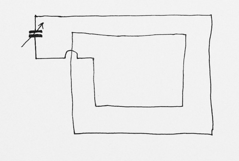
Anyway, I’m getting ahead of myself here. I did make a few changes to the original schematic for my version, so allow me to introduce my rather wobbly circuit diagram -

The differences between my schematic and Paul’s are as follows -

- I added an RF attenuation pot at the antenna input. After building the DR2, I found that using a relatively short piece of wire indoors as an antenna was causing a lot of common-mode hum.  On top of that, I wanted to be able to increase the signal level into the receiver with the use of my regular outside antenna (A 40M dipole fed with 300 ohm balanced feeder.)  Using the attenuation pot allowed me to use the large outdoor antenna without overloading the receiver.  It also created enough separation between the receiver and antenna that the hum problem almost entirely disappeared.

- Earlier versions of the Desert Ratt included instructions for winding the coil on a plastic 35mm film canister and on an IC shipping tube. The DR2 schematic doesn’t include such instructions, but I wanted to use a toroid, so I experimented a bit and came up with a scheme that seems to work OK.  I used a T68-6 former and the turns info is on my schematic above – a T50-7 would take up a little less space. More about this later.

- I had a few 2-position center-off switches that I wanted to use, so I used one of these for a bandswitch instead of the SPST switch in NA5N’s DR2 schematic. I had originally thought that using the 50pF tuning capacitor with no padding would make the upper limit of frequency coverage too high, resulting in too large a frequency swing in one band, but there must have been more stray circuit capacitance than I had anticipated, as the coverage with no extra padding was about 7.3 – 13MHz. This band became the center position.

- I was attempting to power the DR2 from my shack power supply, which is about 45AH of sealed lead acid batteries with a float charger constantly connected.  This also powers my K2, and the DR2 was picking up processor noise from the K2, as well as a low-frequency “burbly” kind of noise of undetermined origin. The problem went away when I powered the receiver from a separate SLA. but I decided to add extra filtering to the power line anyway.  I found that a 1mH choke as well as a 1,000uF electrolytic almost (but not quite) got rid of the unwanted interference on the power line.  For good measure, I added a 0.01uF RF decoupling capacitor across the power line at the input connection.

- I added an AF preamp stage directly after the diode detector to ensure enough power to easily drive a speaker - even with weak signals.

- The inputs to the LM386 are the opposite way around from the way indicated in NA5N’s DR2 schematic.  With the inputs connected as shown in Paul’s diagram, the LM386 emitted a loud screeching sound.  Swapping the inputs cured this. I was not the only person who had this problem, as I discovered from this post in the GQRP Yahoo Group (you need to be a member of the group to read the post).

-  I left pin 7 unconnected. I don’t understand the way that NA5N has it connected to the junction of the series resistor and capacitor connected between pin 5 and ground in his diagram.  Most circuits that use pin 7 call for a decoupling capacitor direct from pin 7 to ground (usually about 10uF).  This helps reduce large signal distortion, though Paul does say that in this application, it may not do a great deal to help and is therefore optional.  I elected to leave it unconnected.

Now for some pictures.  I didn’t want to spend a lot of time constructing an enclosure, so decided to make a simple PCB L-shaped chassis and build the circuit directly onto that.  With the variable capacitor mounting bracket, it still ended up taking quite a while to construct though. All my projects begin like this, with the main components and control being laid out on the front panel, while deciding on the basic layout -

I’ll spare you the words at this point and apologize for all the pictures that are about to come. If you’re living in a remote area and are still relying on dial-up, then I feel a bit sheepish about the sheer number of images to follow!  I’ve talked before about constructing enclosures from PCB material, so won’t repeat that information here. As well as constructing the chassis from PCB material, I also made a mounting bracket for the variable capacitor and a tuning pointer to attach to the reduction drive with 2 small screws – all from double-sided copper-clad laminate.

I applied several thin coats of lacquer from an aerosol spray.  It was sprayed from a distance, resulting in a light, and stippled coating, which you can see in these pictures. I’d rather apply too light a coat than risk overdoing it. The downside of this is that oxidation will being to affect the appearance of the copper fairly soon. Oh well. The capacitor mounting bracket received a thicker coat. You can see the smoother, shinier finish.

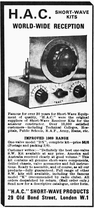
I got the 6:1 reduction drive from Midnight Science. A number of others sell them, and one place that springs to mind is Mainline Electronics in the UK. They are the suppliers for Jackson Bros components (I think they have the rights to manufacture and sell the parts).  They sell on eBay using the name anonalouise.

The enclosure looked a little bit different by the time the DR2 was finished, as the hole for the nylon toroid mounting hardware hadn’t been drilled in the base at this point.

Look at that gorgeous variable capacitor!

A close-up view of the Millen 21050 50pF air-spaced variable capacitor and mounting bracket. This component is silver-plated (the vanes are probably brass), and has double bearings and a ceramic base. It is a very nice variable capacitor, and had never been soldered to before being used in this project. It is at least 35 years old – most likely older!

Boy, was I glad to finish the chassis so that I could start work on wiring it all up.  I decided to build the AF amp first and work backwards, my thinking being that the AF amp would be relatively straightforward. The act of touching the input with a metal screwdriver and hearing a hearty buzz in the loudspeaker would give a welcome psychological boost! If I started by building from the antenna end, I’d have to wait until the entire receiver was built before getting any clue as to whether it was working.

Here’s the chassis with the LM386 amp, the 2N3904 phase splitter, and the 2N3904 preamp built. As has been the case with all my projects since I started using then, I used W1REX’s wonderful MePADs and MeSQUAREs to build the circuit -

Here’s a close-up. The 2N3904 preamp is just below the 6:1 reduction drive, and the 2N3904 phase splitter is to the left of the LM386.  The 100uF capacitor that decouples the supply line to the LM386 straddles it. I read that it is best to ground it to pin 4 instead of to some other point on the chassis to avoid instability, hence the reason for this placement. The other electrolytic that is straddling the chip is the 10uF capacitor between pins 1 and 8 that sets it to the maximum gain of 46dB. The black shielded cable connecting the AF gain pot to the circuit on the PCB is lavalier mic cable.  It has 2 conductors, each of them in it’s own shield, which is ideal for wiring up potentiometers. It is fairly thin and very flexible. I use it in all my home-brew projects. I bought it from a local pro-audio store which recently closed down, so will now need to find another supplier.

In this view, you can clearly see the extra DC supply line filtering that I added, consisting of a 1mH choke in series with, and a 1,000uF electrolytic across, the DC supply. After seeing these pictures, I noticed that there wasn’t very much solder on the joint connecting the choke to the power jack, so I re-flowed the joint and melted a bit more solder onto it.

The power indicator LED’s main function is as a voltage regulator. NA5N marked the various voltages on his schematic for the DR2, and I chose an LED with a forward voltage drop to match those voltages as close as I could.  A green LED in a variety pack I got from Radio Shack had a forward voltage drop of 2.1V, which seemed about right.  The 1N4148 had a forward drop of about 0.65V.

The next stages to be built were the detector and impedance converter/buffer stages.  The description of the DR2 on NA5N’s site gives more info on these stages (as it does for the whole receiver). I couldn’t be sure these stages were working, but bringing my finger close to the diodes resulted in a pleasing cacophony of stations in the headphones – and at a louder level than in doing the same to subsequent stages, so I figured there was some detection/amplification going on :-)

I didn’t know how many turns I was going to use on the toroid, but using the calculator on W8DIZ’ site and an online resonant frequency calculator, I figured that 36 turns on a T68-6 should be a good starting point for the whole winding from pin 3 to pin 6. In Paul’s version, with the coils wound “traditional style”, the tickler winding was about 1/3 of the whole winding.  Coupling between windings is tighter with a toroid than a “regular” coil, so I reduced the number of turns on the tickler. I found that regeneration was occuring at only about 25% rotation of the regen pot, so further reduced the number of turns. Using the turns shown on my schematic at the beginning of this post,  the regen stage moved into oscillation at anywhere between 40 and 50% rotation on the pot, so I left it at that. For the same reason of tight coupling, I used fewer turns on the antenna winding too and because I am using an outdoor antenna, could probably have used even fewer turns.

The toroid was fixed to the PCB with nylon nuts, bolts and washers that I got from my local Ace hardware store.

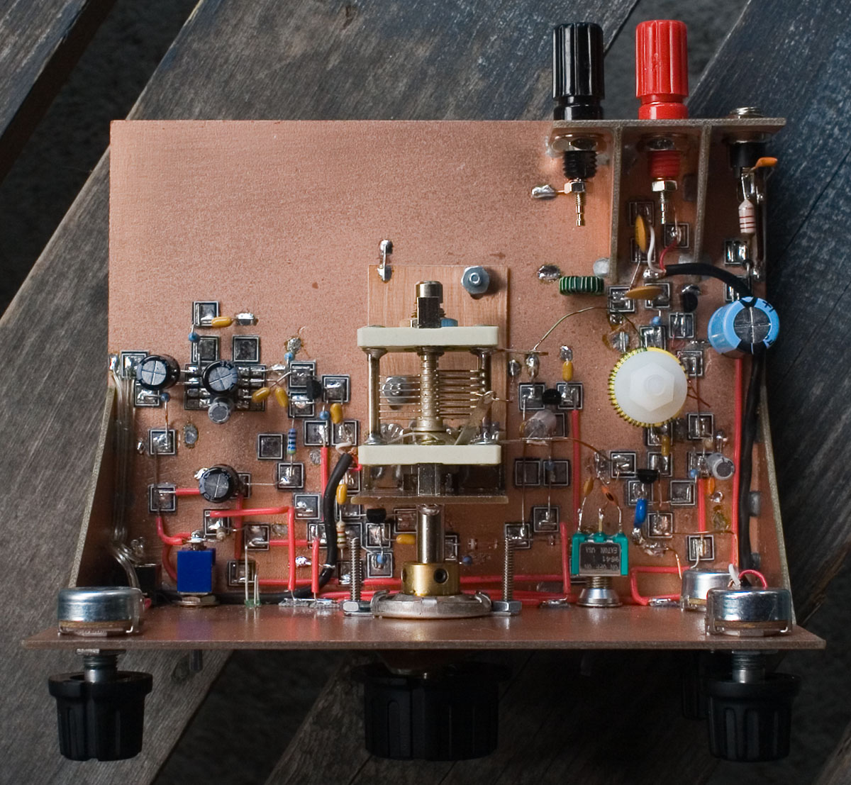
Here are some pictures of my Desert Ratt 2 with the circuit finished -

The red wires running along the back of the front panel are the regulated 2.1V and 2.75V lines.  I would have run them on the main board but ran out of room due to lack of planning, so went vertical.  Incidentally, although I refer to the 2 regulated lines as 2.1V and 2.75V,  the exact voltages aren’t important.  That’s just what they turned out to be in my case.

The RF amp and regen stages can benefit from transistors with high hfe. I got a cheap Harbor Freight DMM that measures hfe from an eBay vendor for under $6 including shipping.  hfe varies depending on the collector current, but I was doing this mainly for comparative purposes rather than absolute values, so the fact that I didn’t know what value of collector current was used to measure hfe in this cheap meter didn’t matter. It just so happened that my 2N2222A’s tended to have higher hfe than my 2N3904′s, so I ended up using a 2N2222A that measured in at hfe = 203 for the RF amp, and a 2N2222A with hfe = 223 for the regen stage.  The other stages don’t require high-gain transistors. NA5N talks about it in this post on QRP-L from 1999. Bear in mind that he was talking about the original version of the Desert Ratt in this post (just so you don’t get confused when he identifies the various transistors).

I did promise that I’d give a bit more detail on the toroid. Mine was wound on a T68-6 former. The main winding was 30 turns tapped at 27 turns from the top (3 turns from the bottom). The antenna coupling winding was 5 turns.  All turns are wound in the same direction. I used 26 gauge wire, but the precise gauge isn’t important. 26 gauge was narrow enough to easily fit all the turns on the former, yet stout enough to lend some stability to the oscillator, as the toroid isn’t sitting close to the board, and the leads are relatively long. When putting taps on coils, I used to not cut the wire i.e. I would simply make a loop in the wire, twist it, tin the twisted part and keep on winding.  Now I find it is easier to treat them as 2 separate windings connected together. If you can get heat-strippable wire, please do – it makes winding toroids so much easier and more pleasurable.  I wound the first winding of 27 turns, stripped and tinned the end, then stripped and tinned the end of another piece of wire, twisted and soldered them together, and carried on winding the last 3 turns in the same direction (this is important).  The separate antenna winding of 5 turns is also wound in the same direction.  I’m afraid I didn’t write down (or if I did, I have since lost it) the lengths of wire used. I did notice that the turns calculator on W8DIZ’ site (linked earlier in this post) was quoting lengths that are too short for the T68-6 former.  All you have to do is wind one turn around your former, measure that length, multiply it by the number of turns you’re going to wind, add an extra inch or two for the leads and, as we say in England, Bob’s yer Uncle and Fanny’s yer Aunt (meaning – you’re home free!)  When winding toroids, I often find that the first 1 or 2 turns aren’t quite as tight as the rest so when I’ve finished winding, I will unwind one turn from the beginning of the coil, then wind an extra one at the end, to keep the total number of turns the same.  Sometimes I will repeat that exercise a few more times until all the turns are nice and tight.  For this reason, I use enough wire to leave several extra inches at each end.

The next picture shows an anti-hiss filter that wasn’t in the earlier pictures, which I tried and ended up removing due to a low-frequency oscillation it was causing at the higher volume settings.   It was a series 0.01uF capacitor and 4.7K resistor connected from pin 1 of the LM386 to pin 5.   From what I have read, too low a value of resistor or too high a value of capacitor can cause the oscillation. I have seen other anti-hiss filters that used a 0.01uF cap and a 10K resistor, so it is very possible those values would have cured my problem. However, I was near the end of the project and itching to move on, so I just removed it. You can also see the 0.1uF capacitors on the inputs of the IC that have been swapped over to stop the uncontrolled oscillation, and are now crossing each other.  You may not have to cross these caps if you plan your layout accordingly -

Other than the problem with the loud screeching that was solved by swapping over the inputs to the LM386 (my schematic reflects the way the inputs were finally connected), the only other problem I had was with what appeared to be a defect in the 0.001uF (1,000pF) capacitor that leads from the tap on the coil to the emitter of the regen transistor.  I wasn’t getting any regeneration at all but on replacing this capacitor, the circuit broke into a nice loud hiss when advancing the regen pot.

I do have one ongoing issue that I hope someone can shine a light on for me, and that is a loud crackling sound when adjusting the tuning capacitor. At first, I thought a dirty rotor connection was the problem, but it only happens when extra padding capacitance is switched in by the band-switch   With no extra capacitance switched in, the tuning is smooth, but on the lower frequency bands, the receiver crackles when being tuned.  I need to try bypassing the band-switch and soldering the padding capacitors into circuit in case the switch is the problem. I’ll report back when I’ve done further work on this.

Incidentally, the main tuning range on mine covers approximately 7250 – 13000KHz.  Switching in a 47pF capacitor changes the range to 5825 – 8050KHz. I’m a bit limited with my receiver and test equipment here, so haven’t yet been able to determine the coverage of the lowest frequency band.

When first listening to the DR2, I had no idea what frequency I was listening to – only that I was probably somewhere between 5 and 12 MHz. I had no antenna connected (and at this point, hadn’t even built the RF amp stage) but started hearing CW. Lo and behold, it was Hank W6SX 180 miles away from me in Mammoth Lakes, CA. His CW signal was coming through well and in fact, this was the only time I have received CW in a satisfactory fashion on the Desert Ratt. There was no antenna – he was being picked up directly by the toroid.  Any concerns I might have had about the sensitivity of this receiver would have been immediately allayed.

I know the main question that is probably on your mind is – how does it sound, and what is it like to use? How does it “handle”? There are some videos of my Desert Ratt 2 in action at the end of this post. Apologies for the poor video quality, but my only video camera is 10 years old (and has a faulty CCD sensor). You’ve probably read articles about regens that describe the many and subtle adjustments that need to be made when tuning a regen in order to coax maximum performance from it. If you haven’t operated a regen before or if it’s been a while, it does take some time to get the hang of getting the best out of it. As you get further away from the setting of the regen pot where it breaks out into oscillation you lose selectivity and gain, so you need to try and keep the control set just under the point of oscillation. Loud stations can overload the detector, resulting in audio distortion, so it’s worth keeping an eye on the RF attenuation pot too. Also, if the attenuation pot is set too high (too little attenuation), you may get breakthrough from stations on other frequencies. There’s quite a bit going on to keep under control, but if you manage to keep all controls adjusted well, you can coax some pretty decent performance out of the set. I think this is why regens appeal to some people – we are incurable knob-twiddlers!

Stability is easily good enough for AM reception and with a logging scale fitted to the front panel, I don’t think it would be hard to find specific frequencies, as the majority of SW BC stations stick to 5KHz channels. In my casual listening so far, I have heard The Voice Of (North) Korea on 9435 and 11710KHz, Radio Habana, Cuba on the 49M band, Radio Australia on the 31M band, coastal station KLB (South Korea) on 8636KHz, the BBC World Service (forget which band or frequency), China Radio International on 9790KHz, WTWW on 5830KHz, and a number of other evangelical Christian stations (sorry, I tune them out and don’t pay them much attention.)

To sum up, you can definitely have a lot of fun and engagement with the bands on this set.  Being a regen, it is not the easiest receiver to operate, but you shouldn’t let that put you off. The best analogy I can think of is to reference the way that although an older British sports car may not have the finesse and performance of a newer sports model, it’s a lot of fun, and it’s lack of suspension gives you an exhilarating feel for the road that the more expensive cars cannot.

The Desert Ratt 2. A logging scale fixed to the front panel would make frequencies in the SWBC bands easy to find. I must do this sometime :-)


Taking Stock, New Desert Ratt 2 Recording, and A New Tut80 Run

$
0
0

When I started this blog almost 4 years ago, I was getting a (very small) handful of page views every day and had no idea that anyone would find it at all interesting or useful. In fact, I don’t think anyone did at first. Then I started building a few things and found that some people enjoyed looking at the pictures of my builds and in some cases, were encouraged to try building things themselves.

I used to think that in order to have a blog, website, or other kind of internet presence, you needed to be really, really good at something or it wasn’t worth putting your stuff out there, but I was missing the point. I think that the point is sharing. I don’t need to be one of the best at something, because everyone does things differently. If I do my best at something, and share the way that I did it, that information could well be useful to someone else who was trying to figure out how to do the same thing. Maybe my approach will present an interesting alternative to someone who was thinking of a different approach.

My last post on the NA5N Desert Ratt 2 Regen is quite a good example of this. I certainly didn’t design it so wasn’t offering anything radically new, but for anyone wanting to build one, there aren’t very many examples on the internet, with pictures, of DR2′s. Of the ones that exist, there aren’t a lot of detailed pictures, with discussion of construction details, all in one place. Perhaps someone was interested in building it, but was wanting to know the winding information for toroids (which doesn’t seem to be available online), or was wondering whether the tuning would be too fine, what kind of reduction drive to use etc. This is why I like to include this kind of information in my posts, in case it can help someone.

Since I sold my FT-817 2 years ago with a desire to rely more on homebrew gear, things have gone quite well. Admittedly the main rig at AA7EE has been a K2, which is not exactly home-brew, but it still felt good to prove to myself that I could assemble a kit of such complexity.

Apologies for the following 2 lackluster photos (it has to do with my inability in using flash to light indoor scenes, among other things) but here are the main bits of gear I have built in the last 2 or 3 years. These are the ones that worked; I left out the partially completed projects (which includes 2 DSB rigs that have working receivers but not fully working transmitters) .

On the top shelf, from left to right, is the 40M DC receiver using a Hi-Per-Mite filter, and an OHR WM-2 QRP Wattmer.

On the middle level is my K2, Fort Tuthill 80 (see news about a further release of Tut80 kits below), and the NA5N Desert Ratt 2 Regen.

On the bottom level you can see the Norcal 2N2/40, the first beta of the CC-20 and the first beta of the CC1 (it’s successor), both sitting on top of the G3WPO DSB80, and the N1BYT WBR Regen Receiver for 40M.

On the desk in front of that lot is a little 2 transistor TX on 7030 based on the Pixie 2 design. I have used it successfully with the WBR for a 100% home-brew on-air experience! -

The reason I arranged all these projects at my operating position and took their picture together is because I wanted to review my progress so far.  My interests are shifting, and it looks like ham radio will be taking a backseat to other pursuits for the next few months. This was a good way of putting a bookend on this period before I begin another one. This color shot shows why I usually drag my projects into outside light in order to photograph them.  I really need to work on my flash lighting skills (note the blown-out red channel on the freq displays – a bit of HDR work with Photoshop could have helped this, but sometimes I just want get on with things and post them!)

In other news, the videos I posted of the Desert Ratt 2 were intended to give a general sense of what this neat little regen is like to tune around the bands.  It doesn’t really give a good sense of what the audio from the receiver sounds like though, as I was using an MFJ-281 ClearTone speaker, which has a restricted audio response. On top of that, I was using the internal microphone of an old compact camera (Canon A80) to record it. To remedy this I made a recording the other night from the speaker jack of the DR2 directly into the line input of a little flash recorder (the Marantz PMD620, if you’re interested) and posted it to Soundcloud.  This will give you a much better idea of the quality of the audio from this receiver. Unfortunately, band conditions weren’t too good, so I wasn’t able to find any consistently strong signals with little in the way of QSB, but this recording of Radio Habana, Cuba isn’t too shabby.  It has been edited down, and the edit points are marked by cowbell sounds. When the signal gets strong, you can hear the wide frequency response and good fidelity of the Desert Ratt 2 -

And finally, I’ve had the pleasure of an e-mail chat with John K5JS, of the Arizona ScQRPions, and he informs me that they will be producing a final run of the Dan Tayloe designed Fort Tuthill 80 Direct Conversion CW QRP TX/RX. They already have the boards and many of the parts, so it sounds as if they just need to order some more parts and have a kitting party. This is no mean feat, as kitting is an awful lot of work. I don’t know when this will be happening, but it is definitely in the works. As you no doubt know, QRP Kits are selling versions of this rig for 15M and 160M, but I think it would be fun to buy another of the Tut80 kits when they come out and mod it for 40M. Has anyone done this? Could they post details of their mods to the Tut80 Yahoo Group if they have, perhaps?

In the meantime, the weather has been getting nicer and combined with the fact that the bands haven’t been in great shape, it’s as if mother nature is coaxing me to get out more. I plan to do just that. My bicycle has a new chain, and the weather is perfect for bike rides.  There’s also a new camera calling my name, which will require new photo software, and the inevitable upgrade of my operating system (I’m still on XP), as well as much time spent outside taking lots of pictures. I’ve been looking at my rather old photo portfolio and realizing that there is much work to be done, and much fun to be had.

Much work. Much fun,  I love it when the two go together :-)


The Etherkit CRX1 – A Handy Little VXO-controlled 40M Receiver Kit

$
0
0

Just a quick post to mention that Jason NT7S has developed what looks like a neat little 40M receiver kit, the CRX1.  It is VXO controlled, covers about 7030 – 7034KHz, and comes with  muting, transmit/receive switching and user-enabled sidetone, as well as a port for connecting an external VFO.  It sounds like a great little receiver for combining with home-brew transmitters and with the external VFO port, there is room for further development. It is all SMT, but with larger-sized SMT components and a board that is not very densely packed, making it a great first project for an experienced builder who wants to get his/her feet wet with SMT.

Here are the specifications (copied and pasted from Jason’s site) -

Frequency Range: Approximately 7.030 to 7.034 MHz (at +13.7 VDC power supply)
IF Bandwidth: Approximately 400 Hz
Current Consumption: 25 mA (at +13.7 VDC power supply)
Power supply: +9 VDC to +14 VDC
MDS: -123 dBm
3rd Order IMD DR: 84 dB
IF Rejection: 74 dB
Image Rejection: 67 dB
PCB dimensions: 70 mm x 100 mm
Antenna Connector: BNC
DC Power Connector: 2.1 mm barrel jack
Phone Jack: 3.5 mm stereo
Key Jack: 3.5 mm stereo
Muting, sidetone (user enabled), T/R switch, external VFO port included

More info here on Jason’s blog.

The CRX1 is not available as a “proper” kit yet but instead of selecting beta testers, as he has done in the past, Jason is selling 8 beta kits on his website for the sum of just $29. Because it comes with minimal documentation, it is only recommended for experienced kit builders. I have built 3 of Jason’s beta kits before and can testify that if you are good at soldering and know how to follow simple instructions, you’ll be fine. The beta documentation probably won’t give you a lot of hand-holding, but if you’ve done this sort of stuff before, you won’t have any problems.

If you’re in the mood for building something and have $29, this sounds like a good idea to me.

NOTE – I just noticed that the Etherkit store is now out of stock of the CRX1 beta. Hopefully we won’t have to wait too long for the production version of the kit.


Building and Installing the K60XV 60M Adapter and Transverter Interface Option For The K2

$
0
0

When I first built the CW-only 10W basic K2 about 2 years ago, I was fairly certain that the basic version was all I would need.  Indeed, at the time, it was. I had made a commitment to operate QRP CW exclusively and was having no trouble sticking to that. So although the basic K2 was a fairly good chunk of change, I was able to justify it. Thing is, that it just begs to be added to. There was plenty of empty space left in the case and although some options, such as the 100W internal PA, promised to relieve me of a good portion of my ham radio budget, there were others that required a lot less (oooh – 160M receive and a separately-switched receive antenna for $40, ooh – SSB for $130, ooh – a nice AF filter for $90, ooh – well, you get the idea.)  So it was that in short order, I ended up with the K160RX option, the 20W internal ATU, and the KSB2 option.  In that post, I did mention that the K60XV 60M adapter and transverter interface option would most likely be the next to be added, and that is how it panned out a few days ago.

Living just 50 miles away from Elecraft is great. I called and spoke with Madeleine in the morning, and the next day this arrived via US Priority Mail (First Class Mail would have cost just 2 bucks and very possibly would have gotten it here in a day also, or 2 days max). The small envelope to the right was an extra headphone jack (just in case.)  Whenever I order from Elecraft, I include a few of the more commonly needed extra parts. Heavily used headphone jacks on the K2 tend to wear out over time – especially if physical stress is placed on them, such as that from a bulky adapter. This probably won’t happen to mine but it will be good to have if, some years down the road, I need a new jack and the current part is no longer available -

Jingles, a new addition to the family (who is blind, but you’d never know it) was trying to ascertain what a K60XV is and what it means for her -

She then figured it out and cast her vote -

There aren’t many parts, and the board doesn’t take long to assemble.  Modification of the main RF board inside the K2 in readiness for the installation probably takes as long, but I’ll get to that a bit later. Here’s the K60XV board after assembly -

I suppose it’s hard to imagine how I can make such a meal out of a fairly simple project by taking so many pictures, but I sure do like taking pictures -

There were a small number of inconsistencies and points I felt could have been made a bit clearer in the assembly manual. I’m going to send Elecraft an e-mail with my suggestions for corrections in the next few days. I won’t detail them here, as it may well confuse if they have been corrected by the time you read this. I will mention the more salient ones in the text of this post though.

There was a diagram showing which side of the board the multi-pin connectors P1 and P2 should be soldered. I found the diagram a bit confusing, so figured it out by looking at the board and the space it was going to fit into in the K2. This photo should help though. look at how wonderfully thick that high-quality board is – and just get a gander at those large plated-through holes. Beautiful!

After finishing the board, the main RF board of the K2 has to be modified to accept the new option.  A jumper has to be removed, and a small number of parts have to be removed and new parts substituted – the exact details of which depend on which revision of the main board you have. Good quality solder-wick is a boon here, and helps to suck up all the solder from those plated-through holes. These boards are well-made, so will not be damaged, provided you have a good iron, good solder-wick, and don’t completely fry the thing :-)  The other main modification is the addition of a length of RG-174 coax to the main board as shown here -

The assembly manual recommends putting a short length of heat-shrink tubing over one end of the co-ax as follows (to prevent the braid from inadvertently making contact with the board). The screws that secure the PA transistors to the heatsink are prevented from falling out with small strips of electrical tape applied to the top side of the board. One of them is visible here -

I thought that it would be a good idea to use heat-shrink tubing on the other end of the cable too, so I did just that.  I had some tubing that was a little narrower in diameter than that supplied with the kit, yet it still fitted over the co-ax, so I used that instead -

A view from the top.  There are 2 sets of holes for the transverter input/output sockets. The user can either install BNC’s in the top cover, or RCA phono sockets in the lower heatsink plate. I decided to go with the latter, and you can just see the 2 phono sockets poking out of the back in this shot. The K60XV board is at the back of the K2, to the left of the K160RX board. The large plated-through holes are so you can still easily adjust the 40/60M, 80M and 30M bandpass filters without having to remove the K60XV board -

One more shot, showing the 3 options I now have installed in the main case (20W internal ATU in the top cover, but that is not visible here, of course) -

On finishing the installation, and switching the rig on, 60M was coming through just fine.  Readjustment of the VCO inductor, L30, was required to keep the VCO voltage within an acceptable range for all bands. This is fully covered in the K60XV and K2 manuals.  I completed the alignment process and was soon hearing much band noise on the 60M amateur band (no activity heard until the next evening) and plenty of AM broadcast stations on both the 60M and 49m broadcast bands.  Funnily enough, the first signal I heard was Radio Havana, Cuba, promoting a film screening that was happening just a few miles away in San Francisco!  I have since heard a few ragchew QSO’s on 60M USB as well as W5GHZ calling CQ on CW, though he didn’t hear me calling him. There was one slight problem with the testing process of the transverter interface part of the option. When in transvert mode, the K2 can develop a low-level signal (1mW or below) to send to the transverter. Firstly, I noticed that when set to an output power of 1mW (at the transverter output phono jack), the K2 was only generating 0.2mW. A few Google searches revealed something that was also in the assembly manual, had I taken the time to read it thoroughly. When using the internal 20W ATU, it has to be taken out of auto mode in order to develop the full 1mW. You can do that either from the menu, or directly from the front panel by pushing the “Display” and “Ant 1/2″ buttons simultaneously. Problem solved? Not quite, as the K2 was now putting out about 50mW – more, but still not enough.

At this point, it was 2:30 am and time for bed. I went to sleep, and woke up the next morning concerned that I had made some kind of boo-boo with the board assembly and/or installation. However, another Google search revealed yet another solution that, had I not been so dog-tired the night before, I would have seen in the assembly manual.  For anyone with a K2 that has the internal 20W ATU, there is a 47 ohm resistor at the input of the op-amp on the ATU control board that can load down the transvert interface to the point where it won’t develop the full 1mW output power. The recommendation is to swap that 47 ohm resistor for a 470 ohm (supplied with the K60XV kit). I did so and – bingo! – the K2 was now putting out 1mW into the transverter output when in transvert mode. I love it when things work :-)

This would be a good time to talk just a little about using the K2 to receive out of the ham bands. Being optimized for the ham bands, with bandpass filters centered on those portions of the spectrum, sensitivity does fall off as you tune away from them. Then as you continue tuning, at some point, the VCO loses lock and you can’t tune any further. However, within these limitations, you can cover most of the SWBC bands with the K2, albeit at reduced sensitivity for some. If you’re a casual SWL only, the reduced sensitivity isn’t as important an issue at it might seem. Each K2 will vary in terms of it’s out of band coverage and sensitivity outside the bands for which it was designed, but this report from Neil WA7SSA will give you an idea of what you can expect.

“But the K2 isn’t set up for AM”, I hear a few people say, “it only receives CW and SSB.”  I have actually seen this argument made in a few online forums and of course, the K2 receives AM quite well, as long you take care to accurately zero beat the carrier. Doing this is easy. Let’s say yours is set up for a CW offset of 500Hz. You select either LSB or USB. I’ll use LSB for this example. Tune away from the carrier until you reach zero-beat with the spotting tone. Let’s say that zero beat occurs at 9580.52KHz.  Subtract 500Hz form this figure and that is where you need to tune the receiver. In this example, you would retune to 9580.02KHz.  Easy! If you were using USB, you’d add 500Hz. Use whichever sideband provides nicer sounding audio. Of course, the width of the crystal filters limits how good an AM broadcast station can sound on the K2, but you get used to the slightly restricted audio. Sensitivity on the 49M BC band is a little low but you can still listen to the stronger regulars on that band (Arnie Coro fans take note!)

Here is a short clip of Radio Habana, Cuba on 6000KHz in the 49M band recorded from the headphone socket of my K2 using the 7-pole crystal filter in the KSB2 option. This filter has a -3dB b/w of about 2.3KHz – less than is ideal for AM SW broadcast reception. This should give you an idea of what to expect when listening to SWBC stations on the K2 -

Funny how that back panel continues to fill up with connectors…….

And if it’s not too much of an imposition, please allow me just one picture of the new addition to the family. This is Jingles. She is 7 years old, blind, and completely adorable. Unfortunately, just like my other 2, she has shown no interest so far in learning the code but she has valiantly (and successfully) taken on the task of leaving little tell-tale pieces of fur on my various homebrew projects as a reminder of her presence :-)


The VK3YE Micro 40 DSB Transceiver

$
0
0

I have attempted to build 2 DSB transceivers now with limited success – a Manhattan version of G3WPO and G4JST’s DSB80 – here and here  (the original kit version which Richard F5VJDD sent me for reclamation, worked fine) and the ZL2BMI rig, here and here. Both of them worked FB up to and including the TX driver stages but as soon as I added the PA, I had constant feedback/oscillation, even when not modulating the TX.  In retrospect, I think a simple partition to separate the driver and final from the earlier stages of the TX would have done the trick in both cases (or even building the driver and PA on the other side of a double-sided board.)

The kit version of the DSB80 that Richard F5VJD very generously sent me was a fantastic piece of nostalgia (I owned one as a young man) and a very satisfying project, but I still wanted to be able to build at least one DSB transceiver from scratch and have it be fully operational.

Enter Joel KB6QVI from stage left. Joel is an avid homebrewer of QRP rigs – both from kits (he’s currently working on a BitX using the original board from India, which he is putting on 40M) and from scratch, Manhattan style. Joel is a fan and big user of the MePADS and MeSQUARES from QRPMe (as am I) and has constructed several QRP rigs using them. Joel and I communicate on Twitter, on which he was singing the praises of the VK3YE Micro 40 that he built. I think he was trying to get me interested in building something again, and his enthusiasm couldn’t help but pique my interest. I’ve made a number of jokes in the past aimed squarely at that trusty favorite of many a QRP homebrewer – the LM386. I usually end up using it with a 10uF cap between pins 1 and 8, which gives lots of gain but also quite a lot of noise.  Joel told me several times about the configuration of the LM386 AF amp that Peter uses in this little rig which still gives enough gain to easily drive a speaker, but has much lower noise than the typical high gain configurations of this chip. Then one of my other non-ham projects came to a temporary pause and I got to looking at this enclosure which I originally made for the second beta run of NT7S’ CC-series transceivers. That beta run ended up using a much smaller board and a smaller custom case, so this blue enclosure has been sitting on the shelf for the last 2 years, just waiting for something to be built in it -

The blue enclosure that was originally made for the second beta run of the Etherkit CC-Series transceivers. The 2 pushbuttons on the front were intended for the CC-Series beta. Only one of them would remain for the Micro 40 DSB rig.

Joel got me to thinking that a little DSB rig in this case sure would be neat, so I rummaged in the parts drawers and fitted the controls and connectors I’d be using if I were to build the Micro 40. I kept telling myself that, as I was trying hard not to commit myself at this point :-) Note the little electret condenser mic insert in the middle. I thought an internal mic would make it easier to use, especially if out in the field. Also note that even though the enclosure is 2 years old, the coat of lacquer I applied has kept the copper looking pretty good -

The trouble is, on seeing a neat little case like this with a few controls and connectors installed, it’s hard not get enthusiastic about actually building it. Notice the small hole drilled above the right-hand pot for the locator lug. I used to break these little spigots off until an incident with my Fort Tuthill 80, in which the volume pot came loose and twisted round. I don’t know exactly what happened, but one of the potentiometer terminals contacted something else, causing a blue LED that was being used as a voltage regulator to blow. From that point on, I started using the locator lugs to help keep the pots in the same position -

At this point of course, I was committed, and set about building what I hoped would be the first DSB rig I’d build from scratch that would actually work.   I have made a few changes to VK3YE’s schematic, and will describe them here.  I hope you don’t mind that instead of using the conventional symbols for the 2 chips, I have represented them as rectangular blocks. It makes it a bit harder to figure out what’s going on with the circuit, but easier to visualize the physical layout when building -

I do have one problem with this rig. In fact, it is the only issue I have with my version, and that is a loud feedback howl from the speaker on going from TX to RX. I am thinking that Peter’s method of directly keying the mic amp with the PTT button would switch the mic amp off a fraction of a second before the relay kicked in and switched the LM386 RX AF amp on, thereby avoiding the feedback perhaps? This loud howl, which you can hear in one of the recordings linked to at the end of this post, was the only thing I wanted to cure. Everything else about the rig is great.

2) I changed the value of the cap that couples the output of the mic amp to pin 1 of the NE602 from 1uF to 0.1uF (100n). On-air reports indicated that my audio was a bit bassy. Admittedly, I was using a microphone that was designed for recording and broadcasting applications, and was way overkill for this use, but I figured it wouldn’t hurt to gently roll off some of the lower frequencies in the TX, regardless of what mic was used. It did help, but I’m now thinking that the value of that 1uF cap in the base lead of the mic amp could stand to be reduced also. Feel free to experiment :-)

3) In Peter’s version, the cap that couples the collector of the BD139 final to the output network is a 47nF.  I didn’t have any of those. I could have put two 100nF caps in series but figured that a single 100nF would work just as well.

4) Peter bypasses the wiper of his tuning pot to ground with a 47nF cap.  I used 100nF.  No biggie. Perhaps I should have used a 10nF instead……..

5) Peter bypasses pin 5 of the NE602 to ground with a 47nF cap. I used 100nF.  He couples pin 5 of his NE602 to the top of the AF gain pot track with a 220nF cap, while I used 100nF. My substitutions are based on what I have in my parts box, rather than any meaningful analysis of the circuit :-)

6) For tuning, Peter uses 2 banks of diodes, each consisting of four 1N4002′s with a switch to achieve the frequency coverage in his rig. With the switch in circuit, both banks of diodes are used, and with the switch out of circuit, just the one bank of 4 diodes are connected between the resonator and ground. He also has a 10uH inductor in series with the ceramic resonator. My 7.2MHz resonator was obtained from hamshop.cz and seems to have very desirable properties. With no series inductor, and just one 1N4004 diode (I didn’t have any 1N4002′s so I used what I had), I achieved coverage of 7207 – 7335KHz.  Placing a 3.3pF cap across the diode (shown as Cx in the schematic) changed the coverage to 7183 – 7295 – almost all of the phone portion of the US 40M band. What luck! Both Jason NT7S and Joel KB6QVI did tests with 7.2MHz resonators from hamshop.cz and achieved very similar coverage. They don’t always have these resonators so my advice would be buy a small stash of them when you see them in stock. These things are like gold! Not all ceramic resonators are created equal – others have different amounts of coverage.

The key advice with ceramic resonators in rigs like this is to experiment in order to get the coverage you want. However, if you are in the US, with the band going up to 7.3MHz, and you have one of those resonators from hamshop.cz, this circuit should give you excellent coverage. Other resonators will most likely give very different results, and you may need to experiment with different diodes, different numbers of diodes in parallel, and perhaps a series inductor (which I believe has the effect of extending the bottom end of the frequency swing.)

7) Pin 1 of Peter’s LM386 is connected to ground via a 47uF cap and a 33 ohm resistor. I didn’t have a 47uF, but I did have a 33uF.  Given the wide tolerances of electrolytics, it probably doesn’t matter much but I substituted a 33uF cap and a 47 ohm resistor. There is an interesting article in SPRAT 116 on page 4 that talks about the use of the feedback resistor and capacitor between pins 1 and 5, as well as the use of an RLC network between pin 1 and ground to create a high gain amp that has a peak at 500Hz for CW reception. With a resistor as low as 3.3 ohms, gains of 74dB and even higher were achieved. This configuration doesn’t use an inductor, or such a low value resistor, but still has plenty of gain without resort to the the more common method of connecting a 10uF cap between pins 1 and 8 – a method that has (in my opinion) done a great deal to give the 386 it’s reputation for high hiss. It does have a lot of hiss when used this way, so don’t do that – use this circuit instead. It is far more pleasing to listen to!

8) I added a 1N4148 diode from pin 8 of the LM386 to ground as detailed in SPRAT 155 page 26. This is designed to help with squeal on going from RX to TX. It did seem to help a bit, but my bigger issue was the squeal in going from TX to RX. Feel free to leave it out, or put it in. Whatever you’d like to do!

9) I really liked the receiver and was surprised at how good it sounded, considering the simplicity. However, at certain times of day, I did experience a small amount of low level breakthrough from AM broadcast stations in the 550-1700KHz band. Joel KB6QVI didn’t have this with his Micro 40 but then, he lives in a less built-up area, about 12 miles outside Medford, Oregon.  I am in the city of Oakland, in the San Francisco Bay Area, and close to many AM broadcasters. This breakthrough didn’t actually stop me from copying any ham stations but it was there and as such, was mighty annoying. Then I noticed that while the problem occurred when I connected the Micro 40 directly to my outside antenna, it disappeared when my ATU was inline. A quick look at the schematic of the ATU revealed that it was a high pass filter (as many ATU’s are). Aha – problem solved!  I installed a simple high pass filter permanently in the receive antenna lead and the breakthrough completely disappeared. The receiver now sounds great.

If you don’t live close to many powerful AM broadcasters, or you are planning to use this rig only out in the field, in the boonies, then you could most likely leave the AM BC band filter out. However, if there is any uncertainty about the circumstances under which you’ll be using it, why not install it? It’s just a couple of toroids and 5 caps (unless you have 2,000pF caps in which case it’s only 3 caps, as you won’t have to double up on the 1,000pF caps).

10) A word about the bypass cap on the TX +ve supply line – the one marked Cy. In Peter’s version, this cap is 220uF. His mic amp is permanently connected to the +ve supply and switched off by a 100nF cap in the emitter lead, which is shorted out by the PTT button on TX. To achieve this, his PTT button keys the -ve side of the TX/RX relay. I understand now why he did this but in my “wisdom” I decided to permanently connect the mic amp +ve supply line to the TX driver final supply line and key them together. A side effect of doing it this way is that when the PTT is released, the remaining charge in the 220uF bypass cap on the TX supply line keeps the mic amp energized for about a second, causing a loud squeal in the speaker. I found that decreasing the value of Cy to 10uF gave a much shorter squeal that I could live with. I am hoping that this lower value of capacitance will still bypass any audio on the TX DC supply line.

As is usually the case with such projects, I built the AF amp first. Touching the input of the amp chip (in this case an LM386) to hear a loud buzzing sound always provides good positive feedback (pun intended :-) ). In the following 2 pictures, the AF gain pot hasn’t been hooked up yet. The curved red lead is a temporary power connection -

The MePADS and MeSQUARES from Rex at QRPMe have become a firm favorite of mine. Every Manhattan project I build uses them. I just realized that I can buy SMT chips from now on if I like, as the sheets of MePADS contain pads for mounting SMT devices too.

The next stage was the point at which things started to get interesting. This is the VXO using a 2N3904 and a 7.2MHz ceramic resonator. Thru-hole resonators for frequencies such as 3.58 and 3.68 are easily available, but ones for 7.2Mhz are a little harder to come by.  When I discovered that http://www.hamshop.cz stocked them, I ordered 3 and gave away one, leaving me with just 2. Now I’m realizing that I should have ordered more, because on firing up the VXO, I found that the coverage with just one 1N4004 diode used as a tuning diode and no series inductor, was 7220 – 7335KHz. Of course, 115KHz of swing is quite a lot but what surprised me more was the fact that this 7.2MHz resonator was happily being pulled so high above it’s nominal frequency. A 3.3pF capacitor placed in parallel with the tuning diode brought the tuning down to 7169 – 7297KHz, which I consider very satisfactory, encompassing as it does the majority of the phone portion of the US 40M band. I like that the upper limit is 7297 as this means I won’t inadvertently transmit out of band. What a cracking little resonator! The resonator is the blue thing just below and to the left of the tuning pot (the top pot) in the photo below -

Fantastico!

Then, things started to get really good, because I built the VXO buffer (an MPF102) and installed the NE602. At this point, I could connect an antenna to determine whether I would be able to hear signals. The first thing I usually do at this point is to turn the power on my K2 right down to 01.W and give a few short bursts of carrier. Even without an antenna attached, the little DC receiver picked it up with no problem and I knew we were in business. The antenna input coil is on the lower left of this next picture. You’ll notice that I have also built the 2N3904 mic amp. The blue wire was a temporary connector to the BNC at the rear of the case, so I could plug in the antenna for listening. If you look closely at the AF gain pot, you’ll see that I soldered a short grounding wire from the body of the pot to the chassis.  Without this lead, you may get hum whenever your hand comes close to the pot.  This doesn’t happen if the pot is used the other way round i.e. if the track is wired between the input of the chip and ground -

This is always the point at which building transceivers gets tricky for me, as I spend so much time listening to the receiver, I lose momentum. I was even beginning to wish that I had set out to build just a receiver.

Here is a synopsis of what had been built up to this point. I had removed the PTT pushbutton to make soldering in that area easier -

You know how when you move house or apartment, you reach a point where you feel as if you’re very nearly done? That’s usually the point at which you are only halfway through (or even less.) All I had to do to turn this rig into a full transceiver, was add driver and PA stages, and I was in business. It wasn’t quite that simple, as I also had to cut and fit a partition, and wire up the transmit/receive switching. Here’s the first view of what I thought at the time was the completed rig. If you’re sharp-eyed, you’ll notice that the electret mic has been replaced by a phono socket.  This was because I kept getting a motorboating sound on TX which was coming from the mic amp. Peter VK3YE said that I should either try a dynamic mic, or try lowering the gain of the mic amp if I wanted to use it with an electret mic.  I decided to take the easier route, and replaced the internal electret mic with a mic socket. That way, I could experiment with different dynamic mics to find the best one. Also, the 2N3053 driver is fitted with a heatsink, wheras the BD139 final is not. KB6QVO said that his driver got warm, while his final ran cool.  For this reason, he used a heatsink on his drvier, but allowed the final to go au natural.  I simply copied him ( it was easier than doing my own research!) -

Well, this little rig works well. See the video at the end of this post to see and hear it in action. As mentioned before, the only issue I was having with the receiver was low level breakthrough from local AM broadcast stations. It was the only downside to what was otherwise a neat little receiver. I won’t retell the story related in point 9) near the beginning of this post, but the simple high pass filter I installed to attenuate signals in the AM BC band did the trick. Here’s a view of the completed transceiver with the high pass filter installed in the receive antenna line. The 2 toroids wound with green wire and the 5 blue caps in the upper left-hand side of the picture are the receive-only high pass filter -

I cut two small triangular pieces out of the bottom of the partition on both sides to allow wires to pass through. One cutout was a little bigger, as it had to allow more wires through. In the following picture, you can just see one of the triangular cutouts (I cut the pieces out with a flush wire cutter – perhaps not the best idea, but the cutter seemed to be undamaged) -

I suppose that at this point extra images just seem gratuitous, but perhaps one of them will contain an extra detail revealed by a slightly different camera angle that will help a hopeful builder somewhere -

This one might be useful in determining what goes where -

Here’s a view of my VK3YE Micro 40 from the back. The hole on the right is unused.  I will cover it up with a piece of electrical tape on the inside -

And here is what this little DSB beauty looks like with it’s cover on, and viewed from the front -

You might wonder about the practicality of covering a tuning range of over 100KHz with a 1-turn pot.  In fact, you are covering this range with just 300 degrees of rotation, which is not much.  The tuning is a bit touchy but I was surprised to find that I got used to it.  If you want, you could use a 10-turn pot for tuning, or a 1-turn pot fitted with a turns counter. The value is not critical – I often use 10K pots for tuning. One advantage to a 1-turn pot for tuning in simple rigs is that you can see roughly where you are in the band with a quick glance. Also, it is great for quickly scanning the band for activity.  A second 1-turn pot for fine tuning would make it easy to exactly tune stations, while still keeping the cost lower than a 10-turn pot or a turns counter. I’m thinking a 100K pot for rough tuning and a 5K for the fine adjustments.

I plug a little MFJ-281 ClearTone speaker into the phone jack and it sounds great, with easily enough volume for comfortable listening. Current consumption is about 30mA on receive with no signals, peaking up to 100 – 125mA on very loud signals. I didn’t measure the current consumption on TX.

Here’s a recording of me in QSO with KE7NCO 180 miles away. At this point, the 220uF capacitor was still in use bypassing the +ve supply line to the TX, causing the very noticeable feedback when switching from TX to RX -

On changing that bypass cap from 220uF to 10uF, the feedback reduced considerably. Here I am in QSO with N7UVH. He is my greatest DX to date, being 736 miles away – not bad for 800mW of DSB (equivalent to 400mW of SSB) -

Here’s a video demonstration of the receiver (boy, I really need a new video camera. This one is 10 years old and limited in resolution!) -

This was me checking into the daily Noontime Net on 7268.5KHz with Jim W6FHZ, who is 180 miles from me -

On the scale of dollars spent for fun and satisfaction had, this little rig is high up there on the list. I built mine with components I had on hand but even if you had to purchase all the parts, I calculated it would cost you around $23 (not including shipping from the various different suppliers.) This is one fun little rig – and it wouldn’t be hard to whip up a simple matching network for an end-fed halfwave antenna, and take a small battery with you for some portable fun.

As an aside, I went to Pacificon last weekend and had the pleasure of meeting Steve the Goathiker, WG0AT. Here he is at the Buddipole booth holding the packet that contains his entire portable station – a KD1JV MTR with a small key and end-fed half-wave antenna. Fantastic!


AM Broadcast Band Dxing – With A $3.50 Radio!

$
0
0

After finishing the VK3YE Micro 40 DSB Transceiver, I did fool around with crystal radios a little, but didn’t pursue those experiments very far. Perhaps they will continue at some point. However, thinking about crystal radio sets did keep me on the subject of Medium Wave AM Broadcast Band listening for long enough to find out about the hobby of Ultralight DXing, which is the hobby of listening for distant stations (usually on the MW AM BC band) using modest portable receivers.  Some enthusiasts cite a receiver price of $100 and less as a cut-off point, and that seems like a reasonable definition.

It’s a neat hobby, and there is a lot to be heard for the dedicated listener. The fact that it can be done with a modest set-up only adds to the appeal.  In 2007, Gary De Bock N7EKX discovered that a little Walkman radio from Sony, the SRF-59, had very good AM performance, and cost under $20 new. Others acquired their own SRF-59′s and also found that considering that it’s just a small, cheap receiver with an analog tuning dial, it has surprising sensitivity and selectivity. Unfortunately, in order to achieve the best performance, an alignment is recommended, as many of them came out of the factory with less than optimum performance. Earlier models, such as the clear-cased prison issue SRF-39FP, had much better factory alignment as well as a higher quality tuning capacitor, but they cost more.  If you’re willing to pop open the case yourself and perform 2 fairly straightforward adjustments, you can have a sensitive, selective and very portable receiver for the 530-1700KHz broadcast band.

How does a cheap receiver like this manage to provide sensitivity as well as selectivity, with excellent image rejection and almost no birdies? Well, take a look at the one I scored on eBay for $3.50 plus $3 shipping, and I’ll tell you -

The Sony SRF-59 uses a low 55KHz IF on the AM band for good selectivity, combined with a local oscillator quadrature mixing scheme that cancels out images – and it operates from a single AA cell with long battery life too!

This receiver uses a proprietary Sony chip – the CXA1129N. They have not released any data on this chip but after it had been on the market for a while, the basic architecture was figured out. This radio uses a low IF of just 55KHz on the AM band. Yes – that’s not a typo – the IF is 55KHz, which gives great selectivity. Think about those other cheapie portables you have that cannot receive a weak station on a channel adjacent to a local powerhouse. The selectivity on this receiver really helps with those kinds of situations. The problem with such a low IF is, of course, images, which would only be 110KHz apart.  Sony get around this by using a quadrature mixing scheme that splits the LO signal into 2, and phase shifts one of the signals, before mixing them back together. This cancels out the images that would otherwise be a serious problem in this design. What a great idea to implement a scheme like this in such a cheap little receiver! It runs off a single AA cell too – reportedly, the main chip will operate down to 0.95V.  On reading about this, I had to have one, and when I found the above used one for just $6.50 inc shipping on eBay, it was a no-brainer.  It came with the Sony earbuds pictured above though when supplied as new, it comes with a set of light headphones.

Out of the package, it sounded pretty good but I had the nagging feeling it wasn’t receiving as well as it could. Gary De Bock, who has performed many alignments on these units for DX’ers, reported that a significant number of them benefited from adjustment. Although the frequency calibration wasn’t too far off on most, nearly all of them needed some tweaking to the 2 tracking adjustments. Mine, it turned out, did too.

I won’t describe the alignment process in detail, as there is all sorts of info about it documented by more knowledgeable people than me. This post by Gary in the Ultralight DX Group on Yahoo Groups, describes it in detail. Also, this page shows how to disassemble and reassemble the receiver and has some good info too.  Both links open in new browser windows. Here is Gary De Bock’s first review of the SRF-59, published in late 2007.

When I first popped the case off, according to instructions I had read, the board is glued to the back part of the case, so the front part is supposed to separate first. It didn’t happen that way for me – my back part came off first. This image also shows the trimcap that is adjusted for maximum signal at about 1400KHz.  If you don’t have a signal generator (I don’t) you can use a weak off-air signal -

This view shows both parts of the case separated from the board -

The view from the other side -

The other adjustment that needs to be made is shown in the next image. The smaller coil is secured to the ferrite rod with wax. The wax is scraped away (I used a small jeweler’s screwdriver) so that it can slide up and down the rod. Then, with the radio either listening to a signal from the sig gen at 600KHz, or a weak off-air signal at or near 600KHz, the smaller coil is slid up and down the rod until the point of maximum signal is found. Gary recommends to use a small piece of tape or woodworking glue to secure the coil in it’s new position; I smeared the wax that I had previously scraped off back onto the coil and warmed it very briefly with a match to melt it again. In this photo, I had already made this adjustment (my coil needed to be moved closer to the main coil for maximum signal) -

A closer view -

You can, if you wish, adjust the frequency dial calibration too. This process is described in the links I have provided, but it was relatively close in the unit I had. There is a limit to how accurate such a basic dial can be anyway, and it is not too hard to figure out where you are if you use powerful local stations as markers. The fact that US stations are spaced at standard 10KHz intervals helps a lot as well.

I have only spent a couple of evenings listening at home so far. The electrical QRM is quite severe in my place at night. It clears up significantly when I walk out into the street, but standing in the middle of my street at night is not the most comfortable position for a long listening session! So far, I have heard stations up and down the west coast, from Mexican “border blasters” on the Mexican side of the border, San Diego, Los Angeles, Las Vegas and up into Oregon, from my home in the SF Bay Area, as well as stations in the central California valley. This is all straightforward stuff – to be hearing stations up to 500 miles distant, but I’m really looking forward to hearing my first Trans-Pacific (TP) DX. There are quite a few powerful broadcasters in Asia that can be heard here on the west coast, as well as inland, when conditions are good.

Anyway, instead of waiting until I had logged some serious DX, I wanted to share my excitement at this neat little receiver. It has reminded me of the pleasure I used to get from simple radios as a teenager. In fact, I even took it to bed last night and went under the covers with it and a flashlight (to see the dial)! The last time I did this with a radio was as a youngster :-)

The appeal of the Sony SRF-59 for me is similar to the appeal that some sports cars hold for driving enthusiasts. In the same way that basic suspension and a lack of luxury features in sports cars like the early British Triumphs made the driver feel closer to the road, there is not much in the Sony SRF-59 to get between you and the AM band. Having said that, it performs better than it’s counterparts from a few decades ago. I love the fact that a newcomer to DXing could, if he/she kept an eye out for a good used deal, get started with this radio, and a small notebook for a logbook, for less than $10. Excellent! I have already had lots of fun for my $6.50, end expect to have much, much more. Stick this in your bag or shirt pocket the next time you go for a walk or hike (or camping), and you’re guaranteed lots of listening fun.

PS – I bought this radio for the AM performance in such a small, cheap radio (and the novelty of the technology used in such a package). It sounds nice on FM but the reason to own this receiver, IMO, is for it’s AM band.

PPS – This little receiver has quite a dedicated set of followers.  Some people have hooked the board up to air-spaced variable capacitors and vernier drives, with larger cases, knobs, input/output jacks etc.  Others have modded it for different bands. With such a cheap radio, there’s not much to lose if you mess up your mod.

PPPS – Some have commented on how the tuning is too fiddly with the small thumbwheel. I haven’t found this to be a problem – I engage my thumbnail with the teeth of the thumbwheel and find it easy to make small adjustments. If you have very short nails, this might not work for you. I saw a mod in which the rectangular slot for the thumbwheel was widened, exposing a greater width of the thumbwheel.


A Tuned Loop Antenna For The AM Broadcast Band

$
0
0

As a follow-up to the previous post, in which I discovered that the Sony SRF-59, though cheap to purchase, offered surprisingly good performance due to a rather creative and interesting receiver architecture. I did some reading up on external antennas to help pull in weak stations.  Among the Ultralight DX’ing crowd (those who DX the AMBC band with small, cheap receivers) FSL antennas are a source of great interest – they offer good gain and directivity in a small and portable package.  However, I had almost all the materials on hand to build a simple tuned loop and as, typically, I don’t pursue these things in too much depth, figured this would be the way to go.

First off, let’s get to grips with the rather complex schematic of this thing. The SRF-59 doesn’t have an antenna jack, so the external antenna will need to be coupled to the receiver inductively, which just makes the circuit diagram even simpler (at this point, it couldn’t really be any simpler) -

There are many different ways to construct a loop of this type. Big ones give more gain with deeper nulls, but space is at a premium for me and as this was an initial experiment, I decided to go for something modest in size.  You can use a cardboard box, plastic crate, or any number of things on which to wind the turns, but I opted to construct a frame specifically for the purpose.  Hardwood is nice, but I don’t have any woodworking tools. A trip to Michael’s craft store yielded a display of balsa and basswood in pre-cut and finished sizes. Balsa is very easy to cut, but is also very soft, and wouldn’t be very hard wearing in duty as a portable loop antenna.  Basswood is a little harder, but can still be cut with a sharp craft knife, so I decided to try a frame made form basswood. I bought 2 pieces of basswood pre-cut to 3/16″ x 3″ x 24″ and a length of 1/2″ square rod to strengthen the frame. At this stage, I have cut 2 slots in each of the 2 main pieces -

I slotted the 2 pieces together and glued 2 pieces of the square section to them with epoxy, to act as strengthening pieces. The square section was held in place with small clamps while the glue was setting. Here’s the finished result -

I wanted to have a rough idea how many turns would be needed, so found an online calculator for exactly this purpose.  I had a nice air-spaced variable capacitor that had been donated by a friend (thanks Jason!) With both gangs in parallel, it has a capacitance swing of 16 – 705pF.  This frame has sides equal to about 16.5″ in length and using the calculator, I figured that 10 turns, with 0.25″ spacing, should tune the AM BC band. Before winding the lopp, I mounted the variable capacitor -

I split a length of narrow-gauge zip cord in two for the loop. Halfway through winding it, Sprat The QRP Cat bit clean through the wire while my back was turned, so I had to solder a new length on in order to continue winding. She also chewed a small part of the frame while I wasn’t looking. It’s a good thing I love that little kitty!

Here’s the finished loop -

The space between the windings is 1/4″, with a wider 1/2″ gap in the middle. This is in case I later decide to use a rod or piece of square section wood as a supporting mast – it can fit through that larger gap -

Another view of the completed loop -

Of course I was keen to try it out, so I switched the SRF-59 on, placed it close to the loop, tuned to a weak station, then tried tuning the loop and moving the receiver around for optimum coupling. Nothing I tried seemed to work and although I could tune the loop to resonate at the frequency I was listening on, it wasn’t enhancing the received signal at all. In fact, reception was better without it. This was all rather dispiriting and I was about ready to throw the towel in and think about adding a few parts to convert the loop to a novel crystal set receiver when, after taking some shots of it outside on my balcony (the 2 pictures above with the concrete on the floor, and the one below), I decided to set up the radio and try it there. It worked! (All the previous tests had been made in my apartment indoors).

For good inductive coupling between the loop and receiver, you want to orient the loop so that both it’s turns, and the turns on the ferrite rod of the receiver, are in the same plane.  The rod in the SRF-59 runs across the top of the case, so this is how it is oriented (you can also place it inside the loop) -

In the above picture, the loop will receive maximum signal from stations to the left and right of the picture (broadside to the winding) – and it does!  My test was only brief, conducted in the daytime, with signals that were of moderate strength. They were of such a strength that there was some noise and static when receiving them with just the radio. On placing the radio next to the loop and tuning it to resonance, all static and noise disappeared, yielding a more pleasant signal to listen to.  To make operation easier,  when orienting the loop for maximum signal, I rested the receiver on one of the diagonal arms in the frame. If the loop were on a stand, one of the arms would be horizontal.

My loop seems to tune well above the top end of the BC band, but doesn’t cover the bit from 530 to about 600KHz.  A fixed capacitor across the variable should bring the tuning range down a bit.  I’ll fiddle around with it in the next few days. I may also make a recording if the spirit moves me :-) EDIT – I did. See below.

I already had the wire and variable capacitor, so this loop cost me $8.58 in wood from the craft store. The SRF-59 receiver cost me $6.50 inc shipping from eBay, so my complete AM BC band DXing set up set me back a whopping $15.08. I like the kind of fun that can be had for such a small outlay :-)

This afternoon, I went out onto my balcony and made a short recording of KZSF in San Jose.

The recording starts with the SRF-59 receiver without the loop, then I place the receiver inside the loop, which has been pre-tuned to resonance and oriented in the direction for maximum signal. I remove the receiver, and then place it back in the loop for comparison. KZSF is not a DX station from my location in Oakland. It is a 5KW station in San Jose – just 40 miles away. It is entirely possible that I could have found a nearby position from which to get a better signal on the receiver without the loop, but this recording was made to show how a loop such as this can provide a meaningful and useful boost to a marginal signal.


Building A WBR Regen Receiver For The 31M Broadcast Band

$
0
0

Note – some of the narrative in this blog-post assumes that you have access to, and have read, N1BYT’s original article on the WBR Receiver in the August 2001 edition of QST.

It has been almost 3 years since I first built N1BYT’s WBR – a regenerative receiver for the 40M amateur band. It was an intriguing design for me, as it employed a Wheatstone Bridge arrangement to minimize oscillator radiation into the antenna without the use of an RF amplifier stage. Unlike older tube designs, more modern semiconductor regens don’t generate as much RF energy, though although you might think that the need for minimizing radiation into the antenna is less, that is not the case. Radiation into the antenna can be the cause of one malady that plagues some regens – that of common mode hum. This circuit avoids that. It is quite a unique design. In fact, unless I’ve missed something, you have to go back to the 1920’s in order to find anyone who was designing along the same lines, as Mike Rainey AA1TJ relates in this post of his.

Such was my pleasure at the performance of this little receiver, I have often wondered how it would adapt to other frequencies. I did briefly try to make a general coverage version of it but for some reason, couldn’t get the regeneration stage to oscillate and gave up on it far too soon. Then, a few weeks ago, I started wondering about building a second WBR, for the 31M shortwave broadcast band. I already had a small aluminum enclosure into which I knew I wanted to put the finished receiver, and some months earlier, had cut a piece of PCB for whatever Manhattan project would find it’s way into the box, so getting the envelope of MePADS and MeSQUARES out and beginning to build didn’t take much of a leap, once I had found the initial inspiration.

A few rough calculations revealed the number of turns that would be required on the toroid for this new, higher frequency coverage, and they proved to be correct. I guesstimated that I should be able to achieve something of the order of 500KHz of coverage, which would allow the receiver to tune the 9400-9900KHz 31M band. I was also hoping to be able to cover up to 10MHz in order to be able to receive WWV and as it turned out, that was indeed possible. As well as a new frequency range, I decided to try a different configuration for the LM386 AF amp. N1BYT uses the 386 in it’s standard high-gain configuration that places a 10uF capacitor between pins 1 and 8 of the chip.  This has the advantage of providing high gain with low component count (an important consideration if you are to engage as many builders as possible), but it is also an approach that results in a lot of hiss. If you’re using a regen, you’re already dealing with a fairly high amount of hiss, so I wanted to at least remove some of that from the audio stages. In his Micro 40 DSB transceiver, Peter VK3YE uses the LM386 in a way that still gives high gain, but is a bit less hissy. Much has been written in the pages of SPRAT on trying to eke more gain from this venerable and much-maligned little chip, and Peter’s circuit appears to be based on LA3ZA’s ideas in SPRAT 116 (page 4). This circuit worked well in the Micro 40 I built, so I decided to use it in this, my second build of the WBR. I also incorporated a pre-amp stage, as suggested by N1BYT in his original article in the Aug 2001 issue of QST.

On completing the receiver, I noticed that it seemed a little deaf. The WBR was a project in the QRP-Tech Yahoo Group (Yahoo membership required), led by Chuck K7QO, and a few builders there also experienced lack of sensitivity. I am wondering if they made the same mistake that I made with both my builds of the WBR – to miss the fact that the full details of Z1 were not published in the original QST article. A later list of corrections revealed that Z1 was intended to be a metal strip measuring 1/8″ x 1/2″ and connected to ground via a short wire. In both of my WBR builds, I used a piece of stiff wire instead of the recommended metal strip, as detailed in the original article, and was perhaps inadvertently placing too little inductance at Z1.  Although Dan N1BYT does warn against increasing this impedance, lest it lead to detector overload, LA3ZA found that an inductor of 0.22uH at this point helped the sensitivity (and presumably didn’t overload the detector). Builders in the QRP-Tech Yahoo group experimented and found values between 0.22uH and 1uH to be optimum. I followed a slightly different route, first adding a 0.3uH inductor, consisting of 9 turns wound on a T37-6 toroid core. This increased the sensitivity dramatically, but also resulted in breakthrough from a local religious broadcaster on 1640AM. Instead of experimenting with lower values of inductance, for some reason, I added a simple BC band trap. At first it appeared to solve the problem, but then I noticed that although the AM breakthrough was much diminished, it was not, in fact, completely gone. At this point, I reduced the number of turns on my T37-6 from 9 to 4 and found that it did the trick. My WBR was still quite sensitive, yet without the disadvantage of breakthrough from strong broadcast signals. I left my BC band trap in circuit but would suggest if you build this circuit, you first experiment with the value of the inductor before deciding whether to add the trap.  Keep the value of inductance as low as possible and depending on where you live, a trap may well not be necessary. EDIT – Jason NT7S has also built a WBR using the schematic published here. He reduced the number of turns on his inductor to just 3 and found no need for a BCB trap, despite having a strong local station at 1390KHz that was causing detector overload when the number of turns on his inductor was 4. It pays to experiment! See the bottom of this post for more info on Jason’s experience with the BCB trap and for a video of his WBR in action. Jason also found that the BCB trap I detailed here does not have an ideal response. Details of that are at the bottom of this post.

I know there are some experimenters who are sitting on the sidelines waiting to build a WBR, but who are a little confused by the various mods published, and want to see more information on a successful build before going ahead with their own. By sharing detailed information on mine, I’m hoping a few more people will be encouraged to build their own version and share their experiences – the internet is a great way to do this. Many thanks to Dan N1BYT for graciously giving me the go ahead to show you a full schematic for this version that I built. The only changes I made to the core part of the circuit (the regen stage and the infinite impedance detector) were to employ a 10-turn pot for the regeneration (with a 33uF cap across it to stop the “whizzing” sound), the addition of the trap, and the substitution of Z1 for a small toroidal inductor, a mod that was first publicized by LA3ZA. The actual value of this inductor may require experimentation on the part of the individual builder but, and this does bear repeating,  it is wise to err on the side of keeping it small in order to avoid detector overload. My 40M WBR uses just a piece of stiff wire for Z1, and I have never heard any kind of breakthrough from all the signals my outside antenna deliver to that defenseless little receiver!


The description of circuit operation is contained in the original article which is readily available to ARRL members. Having read horror stories of unstable and unpredictable regen behavior by some builders (not of the WBR, I hasten to add), I was pleasantly surprised to find that the WBR has smooth regeneration control with no hysteresis, and is overall a tame set to operate. I have read that for solid state circuits, the designs that incorporate a separate Q-multiplier and detector (as does the WBR) tend to work better. Whether this is fact or hearsay, I am not sure. I have found it quite difficult to separate technical fact from folklore in the area of regens. This could be partially due to the fact that many builders, like myself, don’t have an in-depth knowledge of the workings of these circuits. Add that to the fact that regens are particularly dependent on good RF practices and solid physical construction, and I suspect that some designs are declared to be wanting simply because the experimenter didn’t build it properly. Likewise, due to lack of knowledge on the part of many builders, marginal regen designs are published and propagated by people who don’t have the ability to discern whether a circuit is “any good” or not. The world of regens seems to be a mystical and magical one inhabited by equal parts myth and fact.

I used 10-turn wirewound pots for both the regeneration and tuning controls (Bournes 3590S-2-103L). These pots aren’t cheap and if you need to save money, you can use a preset to set the approximate regeneration voltage range, and a regular 1-turn pot for the regen control, as N1BYT describes in the original article. A 10-turn pot does seem to give more precise control over the regeneration though. If you use a wirewound pot here, add a 33uF capacitor between the slider and ground, as shown in the schematic. This will eliminate the “whizzing” sound as you rotate the pot. I have an affinity for 10-turn pots, so I used them for both controls. I like the fact that I don’t have to bother setting the approximate regeneration range with a preset, as I have the full range of control voltages available to me immediately with the 10-turn control. The 10-turn seems to give better control over setting the receiver for the threshold of oscillation. Also, when using the injection of carrier to receive weak AM stations, the regen control can be used as a very fine tuning control in order to set the receiver to zero beat when in exalted carrier reception mode. Adjusting the regen control does have the effect of slightly shifting the frequency of the receiver, which can come in quite useful when wanting to make critical adjustments to the tuning of the receiver. Incidentally, this is a good reason to pay close attention to the physical construction of your WBR. You won’t be able to set the receiver for exalted carrier reception if it’s not stable enough.

The one disadvantage of using a 10-turn pot for the tuning is that you can’t see at a glance roughly where you are in the band. An arrangement of two 1-turn pots, one for bandsetting, and one for bandspread, will be cheaper, and will allow the operate to easily judge where he is in the band simply by looking at the setting of the main bandsetting pot.  Other arrangements might be possible. One thought that comes to mind is the use of an old-fashioned vernier reduction drive with a logging scale connected to a 1-turn pot. This would allow for quite accurate calibration of the dial and of course, the ability to see where you are in the band with one glance. The expense and trouble may not be justified, but if you already have one on hand, it would be an intriguing option. Expanding on this – how about a version of the WBR with plug-in coils for wider coverage? The padder and trimmer capacitors could be included in the coil form so that each frequency range could be adjusted individually. Well – that may be too fanciful an idea, but imagination is free! If you’re using a 10-turn pot, how about one of those turns counter dials combined with your own personalized logging chart? This is an idea I may try to implement in my build of this receiver at some point.

When setting the frequency coverage, you can run a short piece of wire from the antenna lead of a general coverage receiver close to the main tuning coil of the WBR and turn the regen control in order to make the set oscillate. Then, listening to the WBR oscillator in your receiver and with the tuning pot in the WBR turned fully clockwise, set the trimcap for the uppermost end of the desired frequency coverage. Twist the WBR tuning pot fully counter-clockwise, and use the 5K trimpot to set the bottom of the tuning range. With the values given, I was able to get my WBR to receive as high as 10.3MHz and lower than 8.6MHz, giving me the ability to pick any 500-600KHz tuning range within those limits. It would be a fairly simple matter to set the WBR to receive on any desired band of frequencies by changing the number of turns on the coil and/or the value of the 47pF padding capacitor (the capacitor in parallel with the trimcap).

Here’s the basic board. At this point, the only inductance between the center-tap of the main tuning coil (the big one on the yellow T68-6 toroid) and ground is a short piece of stiff wire.  Also, the AM BC band trap hasn’t been built yet (I didn’t know that I would need it). The cables for the various connectors have been bundled together in order to look neat for the picture -

On connecting this board up, the receiver seemed a little deaf, To be fair, although the original article doesn’t mention it, corrections to the article published in a future edition of QST did mention that Z1, the impedance between the center-tap of the coil and ground, should have been drawn as a metal strip 1/8″ wide, 1’2″ long, and grounded to the board with a standard piece of wire. I was using just a piece of wire, as you can see in the photo. This probably wasn’t providing enough inductance. I clipped part of the wire connecting the center-tap to the ground plane, and inserted an inductor consisting of 9 turns of wire on a T37-6 toroid.  This is an inductance of about 0.3uH. Wow – what an improvement in sensitivity! Unfortunately, a local broadcaster whose transmitter on 1640KHz is just a few miles down the road from me, was breaking through. This was presumably caused by detector overload as a result of increasing the impedance at Z1. I added a simple AM broadcast band trap which I initially thought had solved the problem, but later discovered that the breakthrough was still there, albeit at a much lower level. I rewound the T37-6 toroid with 4 turns, for an inductance of about 0.05uH. Bingo! Breakthrough gone! In retrospect, a better way to proceed would have been to attempt to find an optimum value for the inductor that would have given good sensitivity while still avoiding overload of the detector, before adding the trap. Here’s the board after the trap was added, and the center-tap of the coil modified. The stiff wire to ground was cut and a 10M stand-off resistor inserted in it’s place to help with rigidity, before adding the inductor wound on the T37-6 toroid. This is the first version of the inductor, with 9 turns. The later version had just 4 turns -

Time to box it up. I’ve had a couple of small aluminum cases from LMB Heeger that I bought because I thought they’d make great cases for small projects.  It’s their model #143 on this page (available in 3 different finishes) and one thing I particularly like about it is the small lugs on the top cover – 2 at the front and 2 at the back – that prevent the front and back panels from flexing inwards. This feature helps to make it a very stout little case. This enclosure was the obvious choice to make a nice compact receiver out of this version of the WBR -


After a few hours of listening to it (what fun!) the AF amp began to make occasional motorboating-type noises. It appeared that audio peaks were changing the regeneration point and pushing the set into slight oscillation. The battery was still at about 8.5V, so this should not have been happening. While researching possible causes, it occurred to me that in reality, this receiver was going to spend nearly all of it’s time in my shack, meaning that I could run it off the shack gel cell power supply. Instead of solving the issue I took the easy way out, removing the battery holder and fitting a jack for a DC power supply, along with a series diode for polarity protection. The receiver can easily handle the ~0.6V voltage drop from a 12V supply, and if you use the reverse diode to ground method with a bigger 12V supply, it will blow the diode like a fuse if you inadvertently connect the power to the set the wrong way round.  With a small 9V battery, it’s internal resistance should prevent it from passing enough current to blow the reverse diode. Also, you cannot afford to drop 0.6V from a 9V supply, hence the reason for using the method pictured in the schematic. The holes that were previously used to mount the battery clips became tie points for the antenna cable -

My downstairs neighbor’s cat was standing over the WBR in this next shot. You can see his whiskers in the top right-hand side of the frame. I think he’s interested in regens. In these next 2 shots, you can also see the lugs on the top cover that help to make this such a stout little case. It’s a neat little receiver -

From time to time, I am asked what knobs I use for my projects. They are manufactured by Eagle Plastics. I get them from Mouser, though I’m sure they’re available through many other outlets.

The large one I use for tuning is part # 450-2039-GRX (the exact same knob is also available from Radio Shack, and is RS catalog # 274-402

The medium sized ones I normally use for AF gain, RF gain etc are part # 450-2035-GRX

and the small ones I use for AF gain, RF attenuation, and regeneration in this receiver (because space was at a premium) are part # 450-234-GRX

For wiring up the connectors, I use a thin cable consisting of 2 conductors plus a shield. It’s made for lavalier mics, so is skinny and flexible – ideal for wiring up pots and jacks. I used to get mine from a local pro-audio store that recently closed down, so had to find a new supplier. Most places online seem to either want to sell large reels of the stuff or, if they do sell it by the foot, charge too much. I found a place in Connecticut called Redco that sell it by the foot for a reasonable price. On top of that, they will ship via first class USPS mail, which helps to keep the cost down. I haven’t tried any of this new batch yet, but it’s a quality cable made by Mogami (type W2697), and it looks like it will do the trick.

RF connections (like from the antenna connector to the RF attenuation pot) are made with Belden 8215 RG-174/U.  It’s skinny and flexible.

Following are a number of videos designed to show different aspects of this regen, My old camera takes awful quality video (sorry about that) and limits the clips to 3 minutes, which is why there are several videos instead of one long one.

This one shows how the set has quite a narrow bandwidth when set to the point just below oscillation. In all these videos, the WBR is directly driving an external speaker. There is no external amplifier connected -

In this video, you can hear how the audio bandwidth broadens out considerably when the set is oscillating -

Tuning around the 31M band. There aren’t many strong signals, as band conditions generally have been poor. It’s not due to any shortcomings in the WBR -

This video shows how stable a homebuilt regen can be. I could have made mine more impervious to knocks by holding the toroid with a nylon screw and washers, but that might have introduced more long-term drift -

Another video just tuning around. It cuts off rather suddenly at the end -

This one shows how effective the technique of exalted carrier reception can be – and you can do it with a regen! -

It seems fairly sensitive, and quite stable, both in terms of it’s response to physical knocks, and the long term drift. I like regens over direct conversion receivers, because of their ability to demodulate AM as well as CW and SSB transmissions. I suppose that with a very stable VFO (a synthesized one perhaps) a DC receiver could receive AM in exalted carrier mode but with a regen you can actually take it out of oscillation and receive AM with no carrier injection. The regenerative detector is a versatile one.

The only criticism I have of this particular build of the receiver is that I seem to have a noisy LM386. The 386 stage is generating a type of low frequency random scratchy noise that wasn’t present the last time I used this circuit configuration (in the Micro 40). I have heard that there is enough variation in these chips such that you can get a particularly noisy one. This chip was part of a batch of cheap ones I bought from eBay. I just ordered some LM386N-4’s from W8DIZ. They seem to be quality parts from National Semiconductor and because they are LM386N-4’s, they have higher power dissipation and a higher max supply voltage (16V) than the others (12V), which can’t be a bad thing. I may, at some point, put one of Diz’s 386’s in place of my eBay cheapy-chip in this set.   EDIT June 25th 2014 – I just replaced the eBay cheapy LM386 with an LM386N-4 from W8DIZ and the scratchy rumble is gone! The ones that Diz sells are National Semiconductor devices and of course, they still hiss, because they are 386’s being used in a high-gain configuration. With a good 386 though, the noise is just a smooth hiss that is much easier to deal with than the scratchy rumble of the bad part.  Here’s what the sub-par IC sounded like. The hiss is normal for a LM386 used in a high-gain configuration, but that scratchy rumble is most definitely not -

Jason NT7S built a WBR using the schematic in this post. Instead of building it for the 31M band, he built his for the 40 amateur and 41M broadcast bands. If I remember correctly, he set his coverage for 6900 – 7500KHz, which gives him coverage of the pirate BC band at around 6925KHz ±, 40M from 7000-7300, and 41M from 7200 – 7450KHz, though it does make tuning SSB and CW a bit tricky. If you want to make tuning SSB/CW easier, then you can limit the coverage of a 40M RX to just the amateur band. If you’re a hpone-only person, you could have your WBR tune 7150-7300 (in the US) for much smoother tuning! Before removing a turn from his antenna-input inductor, Jason was getting breakthrough from a strong local station on 1390KHz – even with the AM BCB trapin place. He did a sweep of the trap on his scope and here was the result.  The marker is at 1390KHz – the strong undesired signal -

Note how the attenuation of the trap is only about 5dB at the frequency of the unwanted signal. I may take another look at the values of the components in this trap with a view to increasing the cut-off frequency but my first step will be to also remove a turn from my antenna-input inductor to reduce it to just 3 turns and see if I can also manage without the trap.  Thank you for this input Jason!  Jason’s WBR sounds great. It is the first time he has successfully built a regen, and I’m tickled pink that I was able to inspire him to build this one. I don’t think he was disappointed either -

Jason sent me this picture of his WBR, all wrapped up in a smart blue enclosure.  Aluminum for the bottom half, and PCB material for the top half, if I’m not mistaken. I like the attractive pattern of holes for the speaker cut-out. Is the bottom half from an LMB Heeger Crown Royal enclosure, by any chance? Nice! -

Jason NT7S’ WBR in it’s attractive blue enclosure. Jason built his for coverage of 6900KHz – 7500KHz.

This successful build of another WBR is helping to pull me down the rabbit hole of wanting to build the perfect regen. My goal is to build a really good general coverage regen on a nice-sized chassis with plug-in coils for band changes. I am starting to collect parts with this goal in mind and being relatively inexperienced with regens, have many questions in my mind, such as

- semiconductors or tubes?

- separate detector and regen stage, or an oscillating detector?

- an FET or a bipolar detector?

- high mu, or low to medium mu tubes for the detector?

- throttle capacitor with ball drive, or resistive regeneration control?

- toroids or traditional coils?

- any other considerations?

Although I’m secretly looking for a solid technical reason to make my dream general coverage regen a tube design, a semiconductor one would probably be best, as long as I’m not potentially giving up anything in performance. If any experienced regen builders are reading this and have any ideas, I’d love to hear them.

Oh – and the downstairs neighbor’s cat, whose whiskers you saw poking down from the top of the frame in the shot of the WBR from the back? That’s Stephen. He likes regens (I think). Here he is wondering what magical electromagnetic signals there are out there in the ether. He might also be looking at a bug -

Such an enjoyable little receiver. Thank you for the circuit once again N1BYT.


The ZL2BMI DSB Transceiver – An Update

$
0
0

A couple of years ago (gosh – has it been that long?) I attempted to build the ZL2BMI DSB transceiver for 80M.  It was an appealing design, being simple, and capable of being built into a compact space. Eric, the designer, had originally conceived it in the mid 1980’s as a very small rig to be used while bushwalking or hiking in his home country of New Zealand. It first appeared in issue 83 of SPRAT, with an updated version being featured some 16 years later in SPRAT 146. This little rig has spanned many years!

My build looked good but proved that although I may be capable of building things that look quite nice, I’m not always able to make them work.  I’m thinking right now of the wise words of a particular ugly construction guru who would most likely look disapprovingly at my pretty layout that, from an RF point of view, didn’t look so pretty. I am not a great experimenter as, if my builds don’t work after a modest amount of troubleshooting, I have a tendency to retire them to a box on a shelf to keep company with the other projects that “almost made it”.

A few days ago, I received a message from Eric ZL2BMI, who noticed that my version of his rig hadn’t lived up to the aspirations of it’s designer. A number of people made some very helpful comments underneath the post, and Eric also had some ideas. Here’s what he said,

“Originally I developed a prototype and then Bob (ZL2ASO) and I developed it further. Bob is very good at making cases and also milling the boards required for the RF amp. We have made quite a number of changes since the first article and my latest one (which measures just 75mm x 50mm x 25mm) is dual 80/40 m and about 5 watts out – and weighs about 110 gm) However, to come to the problem you had with output carrier on transmit – we did not have this problem with our first two or three rigs, or not to any great degree, probably because the power output was not much above 1.5watts. Then it started to show up – particularly with a 10 watt version I built for an amateur who goes hunting and wanted something with a bit more power to use in the backblocks. Looking at the circuit I realized that with the front-end coil tuned to the frequency in use, and still connected to the NE602, it would pick up some signal on transmit, and this would unbalance the 602. I confirmed this by watching the output (no audio in) and shorting the top of the aerial coil to ground – which killed the spurious output completely. I tried a diode switch – but while it helped, it wasn’t perfect (still 0.6 volt across it). Then I played with transistor switches and discovered something I had never realized – the collector of a transistor does not need volts on it to work. The simple fix is this – an npn transistor (small signal type eg BC547 etc) – the collector goes to the top of the aerial coil – the point where the cap goes to pin 2 of the 602. The emitter goes to ground and the base goes via a 10k resistor to the +ve T line. Despite the fact that the collector is at ground potential (via the coil), it has no effect on the tuned circuit with no volts on the base, but switches the signal hard to ground when +ve is applied. We have since modified all of the approx 12 sets we have built (most for others who use them in the field), with the addition of this transistor – usually mounted right on the top of the coil – to great effect.

Eric also writes about my build,

“It’s possible that leaving the input of the NE602 “open” (rather than grounded) may have left it susceptible to RF pickup. Or it may be that there is some other RF problem. We tended to use the same layout for all our rigs, and I know that some who varied the layout too much had problems. I have built about 7 or 8 of these rigs now, and since the addition of the “front end shorting transistor” there have been no problems with the RF “leakage”. I have retrofitted it to all the earlier ones I made for others. I will try to get some photos of my smallest rig in the next day or two and email to you. There are a few other small mods – to stop a “skwark” when going from transmit back to receive – but this is really just a resistor; and one or two others, mostly to do with getting more power out by better matching of the output transistors.”

Looking back at my notes, I did try disconnecting the antenna coil from the input of the NE602 on transmit, but they don’t show whether I actually shorted that input to ground on transmit. It’s very possible that I didn’t try that.  I have a feeling there may also be some problems with my layout.

My head is full of regens now, but I wanted to get this information up on my blog and into the hands of anyone who is thinking of having a go at this neat little rig. Eric, as promised, also sent some photos of his smallest rig. It’s a 2 band 80/40 version. -

ZL2BMI DSB Transceiver – 80/40M Version (Photo by ZL2BMI)


ZL2BMI DSB Transceiver – 80/40M Version (Photo by ZL2BMI)

The antenna coil is the one close to the front panel with a ferrite slug inside, and you can see the transistor he added to short it to ground on transmit -

ZL2BMI DSB Transceiver – 80/40M Version (Photo by ZL2BMI)


ZL2BMI DSB Transceiver – 80/40M Version (Photo by ZL2BMI)


ZL2BMI DSB Transceiver – 80/40M Version (Photo by ZL2BMI)


ZL2BMI DSB Transceiver – 80/40M Version (Photo by ZL2BMI)

Eric also sent along a schematic which looks like the way he gets the higher output power in his newer version.  I do believe he has written something for a future issue of SPRAT on this, so we may get a little more information in the next SPRAT.

ZL2BMI DSB Transceiver – 80/40M Version (Photo by ZL2BMI)

Thanks for the info Eric – and thank you for sending along the photos!


My $10 Fleamarket Find!

$
0
0

I usually roll out of bed anywhere between 6 and 7:30 in the morning, prompted by cats who want to be fed. The last couple of mornings, after feeding them, I have gone back to bed and napped for a few more hours. This is not normal for me, but probably has a lot to do with the very warm weather we’ve been having recently. So it was this morning, and was the reason that by the time I got a message on Facebook from my old neighbor Sue that the California Historical Society was holding an auction and fleamarket in the city of Alameda today, the event was already underway. I rushed in the shower and hoofed it to the bus stop as soon as I could. I didn’t even have time to stop off at the ATM so when I got there, I only had $22 in my pocket. $5 paid my admission, leaving me with just $17 to score a cool deal. There were some lovely old vintage pieces in the auction but like all good cheapskates, the piles of “junk” in the fleamarket at the back were what drew me in. This is what I found -

My $10 fleamarket find. The marks on the front panel and on top of the cans were just dust and dirt, and cleaned up nicely with a damp rag.

What attracted me was the National ACN dial, fitted with a “Velver Vernier” drive. They were in good shape and the reduction drive operated smoothly. The drive and dial alone were well worth the $10. The dial is marked “Frequency cut-off in KC” and calibrated from 1.8 to 25. On the back, there are 2 1/4″ jacks, marked “In” and “Out”. The rectifier tube is a 6X5GT and the other one is a dual-triode 12AU7. This looks to be a tunable audio low-pass filter. I was hoping that the wiring on this homebrew project would be done poorly, so I could easily justify cannibalizing it for parts. Sadly, this was not the case. This is what it looks like without the bottom cover -

I already have a National ACN Dial like this one, and several National “Velvet Vernier” reduction drives, but this one has the smoothest action of them all. If I wanted to restore this audio filter, I’d need to at least recap it but as nice as it is, I’m thinking that the same function can now be attained more easily with solid state devices (so why would I want this one?) The front panel is thick, and the chassis stout and solid. If I were to cut out the top of the chassis and replace it with a new aluminum plate, there are any number of projects that could be built around the dial, vernier and that 3 gang variable capacitor. The variable capacitor wouldn’t be ideal for a high stability VFO, but it might work well for a preselector for MF thru’ HF, for example -

Sitting on the bus on the way back home, as I clutched this on my lap, the guy sitting next to me asked, “Is that a flux capacitor?”

So what would you do this with this if it was sitting in your shack?


N8RVE’s WBR Regen Receiver

$
0
0

I’ve been chatting with John N8RVE via e-mail for a while now. He built a little receiver that I dubbed “The Rugster” - it’s a direct conversion receiver consisting of a standard NE602 front end, with a “poor man’s varactor” (1N4001) to tune the bottom 50KHz of 40M. The AF stages and narrow filtering are provided by the 4SQRP Hi-Per-Mite filter.  John’s Rugster initially drifted a little, then when he used NPO caps in the frequency sensitive  parts of the circuit, the drift issue cleared right up (funny how that happens!)  He was very happy with his Rugster, as am I with mine.  It’s always great to hear of fellow homebuilders successfully completing projects.

More recently, John built a WBR regen receiver with a FAR Circuits board that he picked up at Dayton, and sent along some pictures of the final receiver. Talk about a neat and original enclosure – he used a piece of plexiglass and a reticle from an oscilloscope -

That’s a neatly wound toroid John -

John says that it sounds great, though he uses an outboard amp, as the audio level was low.  I’m thinking it shouldn’t be too hard to construct a one-transistor pre-amp ugly-style, so that this receiver can pack a little more audio output.

Great job John, and thank you for sharing your success with us!


The HumanaLight – A Flashlight That Uses Your “Dead” AA Batteries

$
0
0

A couple of weeks ago, I was spending a very pleasant hour or so waiting in the front yard for the mail carrier to deliver some packages of vintage radio parts I had ordered a few days earlier. My neighbor’s cat Stephen was lounging around with me, and it was one of those perfect afternoons where time almost stands still. It was warm, with a slight breeze and as Stephen and I lay on the garden path looking up at the sky, I nearly forgot the reason for my being out there in the first place.

Eventually, the mail carrier arrived and Stephen took off. He’s an indoor/outdoor kitty, so mistrust of humans he doesn’t know is a valuable trait. The mailman handed me two packages packed with vintage dials and other parts – and another, smaller packet from my friend Thomas Witherspoon K4SWL. Inside was a kit to build the HumanaLight – a flashlight that uses the residual energy in depleted AA batteries to provide useful light for much longer than would be possible without this neat circuit -

The HumanaLight is based on the “Joule Thief”, a self-oscillating voltage booster that boosts the low voltage from a nearly depleted AA battery in order to light an LED. It does this, of course, at the expense of a greater current draw from the battery but it’s not as if this energy was going to be used otherwise.

Thomas is the founder and director of Ears To Our World, a non-profit organization whose main goal is to empower people living in extreme poverty or war-torn areas of the world by distributing self-powered short-wave receivers to them. It may sound like a simple thing, but for people living under very difficult circumstances, access to reliable news and information from areas directly outside their own can be a lifeline.  This page explains it more succinctly.  Many of the radios that ETOW distributes incorporate LED flashlights, and it was noticed that this feature of the radios is very popular. If you don’t have reliable electrical service, a flashlight that can be powered by hand-crank or batteries charged by solar cells is a very useful thing to have.

The HumanaLight was inspired by the LED lights on the self-powered radios distributed by ETOW. It’s a neat idea – a little LED light that is powered by a novel power source – the residual energy in nearly-depleted AA batteries. When the voltage in the AA cells you are using to power your portable radio, camera, or other device, has dropped so low they will no longer power it, there will most likely still be enough energy  in them to run this little flashlight for a useful length of time.

The HumanaLight comes with an easy to follow set of step by step instructions for assembly. It would be an ideal kit for a beginner -

Stephen strolled along to see what was going on and decided to inspect. Luckily, it passed the whole process without a scratch -

Taking a brief break from the rigorous quality control process -

Assembly is simple – just a few components to solder into the board and bingo – you’re done!  The kit comes with two white LED’s – a standard size one, and a jumbo one. You also have the choice of mounting the LED either with the leads bent at right-angles so that the LED points forward like a flashlight, or you can solder it flush with the board so that it points upward. I couldn’t decide, so I didn’t solder it in at all for these pictures, just placing the LED through the mounting holes without soldering (I later decided on using the jumbo LED and soldering it in flashlight-style).

For comparison, I first plugged in a fully charged NiMH cell with an unloaded voltage of 1.35V. You can’t really get an idea of relative brightness from these photographs, as the LED completely blows out the highlights but here’s the picture anyway -

I then tried an old battery that measured 0.76V unloaded -

You can’t see it too well in the picture, but the “dead” battery gave noticeably less intensity. However, if I was in such a situation that I needed an emergency light, and all I had were a few nearly exhausted batteries, I’d be glad for this much light to see my way around. I had another cell in a similar state of depletion, but no others to try. I have read comments from others who tried AA batteries with unloaded voltages of ~0.4V that didn’t work. This circuit does usefully boost the voltage available from a near-depleted cell but it obviously has limits. A cell with an unloaded voltage of ~0.7V isn’t useful for much though, so it’s great that you can use the HumanaLight to get some useful emergency light from it.

The board has a handy hole at the opposite end from the LED – no doubt for a lanyard or suchlike. You could also use it to hang the HumanaLight on a nail on the wall for easy access during an emergency. It would be fun coming up with an enclosure for this – perhaps some thin-walled tubing. I have left mine as is. I plugged a freshly-charged cell into it and switched it on Friday night. Although not an intense beam (it is, after all, a single LED) it raised the ambient light level in my room enough to make it a bit harder to get to sleep, so the next morning I moved it into the hallway where it remains. I’m keen to know how long it lasts.

The HumanaLight is available from Universal Radio here. With circuit design by Gregorgy Majewski and board layout by David Cripe NM0S.  It’s a neat kit and if, like me, you believe that shortwave radio is still a very relevant and useful way to get news and information to people living under very difficult circumstances, purchasing it is a great way to contribute to the cause.


The Sproutie – A General Coverage Regen Receiver with Plug-In Coils

$
0
0

I’ve mentioned before in posts how one of my first shortwave receivers as a teenager growing up in England (in fact, possibly the first) was a one tube battery-operated regen built from a kit. Many of the popular electronics magazines at the time, including my favorite, Practical Wireless, carried advertisements from a company called H.A.C. (“Hear All Continents”) who sold kits for simple HF regenerative receivers. This was the ad I remember best. To the teenage me, this receiver was the holy grail. With this receiver, there would be no stopping me. I would be the king of the hill, if only I could have this magnificent shortwave receiver -

Ads like this for H.A.C. shortwave receiver kits were common in the UK up until the early 1980’s. Image taken, with permission, from Louis Meulstee at http://www.wftw.nl/

I saved my pennies and eventually sent off for the H.A.C. Model DX Mk. 2. It wasn’t as fancy-looking as the one picitured in the ad, as it didn’t have a front panel or a calibrated dial but hey – those kinds of regens were only for the truly well-heeled, and I was just a kid with a modest allowance. The kit that arrived used an HL23DD valve (or equivalent). It was a battery operated double diode triode, with a coated filament, to maximize emission from the filament that operated from the low voltage of just 1.5V (2V maximum, with a current consumption of just 50mA). This set didn’t have a front panel or a calibrated dial, sporting just a modestly-sized aluminum chassis with 3 chicken head knobs on the front, but with my 2000 ohm headset and 90V high tension battery, I truly was the king of the shortwave hill. I don’t have any pictures of my H.A.C. Model DX Mk. 2, but featured here are pictures of someone else’s taken from Louis Muelstee’s great website, which is where the ad shown above came from too.

The H.A.C. Model DX Mk. 2 cost me all of £14.50 in the late 70’s. (Photo taken by Philip McNamara and taken, with permission from Louis Meulstee at http://www.wftw.nl/)

This one tube regen used an HL23D double diode triode tube with low current consumption 1.5V filament. The blue lead on the left leads to a connector that plugged into a 90V high tension battery. (Photo taken by Philip McNamara and taken, with permission from Louis Meulstee at http://www.wftw.nl/)

Truth be told, this wasn’t exactly the most sensitive receiver ever created, but it mattered little to a teenager in England in the 1970’s, with plenty of loud shortwave broadcast signals. There was much to keep those high impedance headphones firmly glued to my head. They were fairly cheap quality, and the way the metal headband tensioned the earpieces against my ears made them a little red after 30 minutes of use. Did I care? Not at all – I wore them for hours on end, as I was captured by the sounds of Radio Nederland, Radio Prague, Radio Tirana Albania, Radio Moscow, The BBC World Service and many other broadcasters, as well as all the weird-sounding utility stations and the very mysterious numbers station from East Germany. I had no idea back then what it was, but the female voice announcing strings of numbers in German was strangely compelling. Every day, I would rush home from school, eager to get into my bedroom, plug the low-tension battery in, wait for a short while for the tube filament to heat up, then connect the high tension battery and clamp the headphones to my head, cup of tea by my side, as another listening session began. Weekends were heaven. As soon as all my homework was out of the way, there was nothing but blissful hours and hours of potential shortwave listening time stretching ahead. From time to time, the 90V battery would run down, and I would walk the 2 miles into the village of Astwood Bank to buy a new one from the local gas station.  It didn’t take me long to figure out how to power the filament from a transformer in order to save money on low tension batteries. I eventually figured out how to do the same for the high tension supply too. On good days, I could even pick up some local amateurs on 80M SSB. Man, I was indeed the king of the shortwave hill! At the back of my mind, though, was the idea that somewhere out there was still a truly dreamy shortwave receiver – one that had a front panel fashioned from a sheet of aluminum, and a calibrated tuning dial. It only took me until the age of 50 to finally own one of those only-in-your-dreams kind of receivers.

Which is what this blog-post is all about.


I’ve had some encouraging success with regens recently. Both the WBR and my modified version of the the WBR, which I built for the 31M BC band, worked well, with no common-mode hum, instability, or any of the other kinds of naughtiness that sometimes accompany the operation of regenerative receivers. There was one main thing about the WBR’s that limited them for me, and that was the fact that they only operated on a limited range of frequencies. After building these 2 receivers, the next logical step was to build a general coverage regen with plug-in coils. I wanted a set that was built solidly, with a reduction drive and a calibrated tuning scale, so that I could prove to myself something that I already knew – that a regen, properly constructed, can serve well as a shortwave receiver rather than just as a novelty, which seems to be the category most people have placed them into these days. I’m reminded of a comment on a discussion forum I saw recently, in which a gentleman was talking about a regen he had built once. It was sensitive, received lots of stations, and gave him much enjoyment, he said, but he never really knew where he was on the band. “Well of course you didn’t!” I thought to myself, “but that’s not because it’s a regen – its because when you built it, you didn’t build it with a calibrated dial. It’s not the regen’s fault you didn’t know where you were on the band – it’s yours!”

Charles Kitchin had a design for a receiver which caught my attention. It was published in the Feb 2010 edition of CQ Magazine and consisted of an oscillating detector feeding a 2-stage amplifier consisting of a low-noise FET-input opamp acting as the preamp. The preamp had a low-pass filter with a variable cut-off point, as well as an extra capacitor in the audio chain that could be switched in to give a nice lift to the lower frequencies, for those times when you have a nice strong signal and want a bit of bass boost. This preamp drives an LM380, which makes for a much lower noise AF amp chain than the default in these types of receivers that employ an LM386. On top of that, there is provision for a line out jack for recording. I was interested – regardless of the front end I used, this could definitely be the AF amp for a “serious” regen!

Before I had even fully decided on the finer details of this project, I assembled the AF amp on a separate board. I wanted this to be a somewhat modular receiver, with the AF and RF sections built on different boards so that if either section didn’t work out, I could try a different one. I wasn’t entirely convinced that the value of Hammarlund tuning capacitor that I was planning on using was going to be ideal, so I wanted it to be a relatively easily swappable part with other tuning capacitors of different value but with the same form factor (of which I own a few). If I was going to go to the trouble of building something like this on a nice chassis, I wanted to give myself the maximum possible chance of succeeding.

Here is the schematic of the AF board. It is a little different from the version originally designed by Mr Kitchin (though not by much) as I will explain -

In Chuck’s original version, the 2.2K resistor on the input was 5K.  The ratio of this value to the value of the 100K resistor between pins 2 and 6 of the AD820AN determine the gain of the stage, and I wanted a bit more. Also, the LM380 was motorboating when the AF gain pot was set to anything higher than half-volume, so I added the 10 ohm resistor in the supply line and bypassed it with a 470uF electrolytic, which stabilized it nicely. Another small issue I experienced with mine was that when the AF gain pot was at absolute maximum volume, rotating the low-pass filter pot caused clicks and “bloops” in the speaker. It seemed to only happen when the slider of the pot had finished traveling over the carbon track and had actually made contact with the metal that formed the hot end of the control. I didn’t know what caused this, and I suppose it’s a bit of a “kludgy” fix, but I reasoned that placing a low value resistor at the hot end of the pot would, in effect, prevent the amp from being driven at absolute maximum volume but that the difference between this level and the absolute maximum volume would be so small as to be barely noticeable. I tried a 10 ohm resistor, which reduced, but didn’t completely eliminate the clicks and bloops. A 47 ohm resistor did cure it though, and I was left with a volume control that operated smoothly, and a variable low-pass filter pot that also operated smoothly. Very satisfying! Finally – about those 2 capacitors marked CT. They are coupling capacitors that help to determine the amount of low-frequency signal that is passed. In N1TEV’s original design, they were both 2.2uF, and I found these values to be a bit high for my tastes, making the audio a bit too bassy. This is all a matter of personal taste of course. I used 0.22uF for CT in both positions and found that it gives a pleasing lift to the lower frequencies. It is not always apparent on the internal speaker (in which case a higher value would be better), but is more noticeable when using good quality earbuds or headphones, and on recordings. Use whatever values work best for you. The 0.1 and 0.01 uF bypass capacitors on the 12V line were placed so as to bypass the 12V supply directly at the point of entry into the chassis. I wasn’t experiencing any problems before fitting them but it can’t hurt to decouple the power supply the very moment it enters the enclosure can it? Nip these things in the bud before they even have a chance to get a foothold, I say :-)

Here’s the AF board as I first built it, before changing the 5K resistor on the input to a 2.2K resistor, and the two 2.2uF capacitors to 0.22uF parts – and before adding the 10 ohm resistor in the 12V supply line and the 470uF capacitor to bypass it. The lengths of lavalier mic cable for the variable low-pass filter and the AF gain potentiometers have already been soldered in place, and they exit through holes drilled in the board. The headphone jack and DC power connector are temporary, for the purpose of testing. The Manhattan pads are of course, as always, W1REX’s MeSQUARES and MePADS -

The front end is a very standard design. It is the same configuration (and indeed the same circuit) as used in the WBR, with the exception that the tank (unlike that in the WBR) is unbalanced. This same arrangement was used in Nicky’s TRF, as featured in issue 70 of SPRAT, and I believe the original circuit was developed by GI3XZM. I wanted this receiver to be usable over a wide range of frequencies, and in keeping with my “modular” approach, wanted the receiver to be as versatile as possible. A plug-in coil system, with both gangs of a dual gang variable capacitor, as well as the fine tuning capacitor, all available at the pins of the coil base, allows for a lot of flexibility when winding coils for different bands. The user decides, when constructing a plug-in coil, whether to include padding or series capacitors for the main tuning and fine tuning capacitors, as well as choosing whether to use one, or both gangs of the tuning capacitor. In this way, with some calculations and a bit of trial and error you could, say, wind a coil to cover a large segment of the HF spectrum, or a single narrow band of frequencies. If, after some listening, I decide one day that I am particularly interested in the 16M broadcast band, I can construct a coil to cover just that one band. Neat!

The J310’s in the RF amp and the detector stage could be any similar N-channel JFET such as the MPF102 or the 2N3819. Likewise, the two 2N3904’s could be most any small signal general purpose NPN transistor. I originally fed the output of the J310 “infinite impedance” detector stage directly into the input of the AF amp board, but quickly discovered that the gain wasn’t enough to comfortably drive a loudspeaker. Had I done a few quick calculations beforehand, I would have realized that. I wanted to take advantage of the fact that the output chip is an LM380, by driving it enough to make a loud noise into the speaker! Adding the single 2N3904 preamp stage after the detector solved the problem nicely. I have built enough of these simple receivers that can drive “a small speaker to a comfortable volume in a quiet room” :-) No more!

As with any circuit of this type, the RF stages, and the frequency-determining part of the circuit especially, should be built with short leads, and stiff wiring. Top quality components will help.  The two 330pF capacitors in the feedback circuit of the 2N3904 oscillator stage should be NPO’s (or C0G’s – same thing), as should the 39pF capacitor. The coils were wound on toroids, and the coil assemblies mounted in octal tube bases. I spent a great deal of time on W8DIZ’ site, using his online calculators to figure out the number of turns required for varying degrees of coverage. Unless you build a receiver with the same variable capacitors, and use a very similar physical layout, you’ll need to do your own calculations, and then be prepared to tweak the final values of inductance and capacitance to get the coverage you want. Incidentally, I used a Hammarlund MCD-35-MX dual gang component for the main tuning capacitor. It was this one that I got a deal on over a year ago. The official specs say that each section has a capacitance of 6 – 31pF, but I also had to make a rough estimate of the stray and circuit capacitance when calculating the required values of inductance and capacitance to cover each band. My fine tuning cap was a Hammarlund MC-20-S, and I had to include the capacitance of that in the calculations too. This is the online calculator on W8DIZ’s site for the T68-6 core. He has similar calculators for all the popular toroids. Very useful stuff.  Note – for some reason, the calculator doesn’t always estimate the correct length of wire that needs to be used. This is easy to work around. Just wind one turn around a toroid measure it’s length, multiply that by the number of turns, and add a few extra inches for good luck (and pigtails).

Here’s a view of the RF board as initially built, before adding the extra (pre-AF board) preamp stage -

Here are the details of the coils wound so far. I have every reason to believe that this receiver can go quite a bit higher in frequency than the 15980KHz which is at the upper end of the range for my highest frequency coil so far. I ran out of tube bases and need to get some more, but did wind a temporary coil which oscillated (and received signals) at around 24MHz.  I’m just not yet sure how sensitive and stable the set will be at that frequency. Your values will probably be different, but here is the info on my coil set so far. After a little while looking at it, it should make sense -

Note – if you wind too many turns for the link winding, you may find that you have to turn the regeneration control nearly all the way clockwise in order to reach oscillation, or you may not be able to reach it at all, as the link winding loads down the oscillator. If this occurs, remove a turn or two from the link winding. It is particularly easy to do this on the higher frequency bands, where the main coil (L1) doesn’t have as many turns. Also, it is easy to overload the detector (as it is with all regenerative receivers). I use my Sproutie with a large outdoor antenna and find that on the lower bands, I usually only need to operate the set with the RF “gain” control set halfway. If I were winding these coils again I would use fewer turns for the link windings on several of the coils (the lower frequency ones).

The coils were constructed in two different ways. The lower frequencies used a larger T68-6 core which I mounted with nylon hardware. I first took a #10 nylon bolt, cut the head off, and epoxied it into the hollow center spigot of the tube base thus -

Before adding the toroid, any jumpers and capacitors were soldered in place (this is going to be the 3050- 3950KHz coil). The soldering’s a bit messy, but it was the first time I had soldered one of these things -

A couple of nylon nuts followed, then a nylon washer, and then the toroid, topped off by another washer and finally, another nut -

The higher frequency coils used T50-7 toroids, which, being smaller and lighter, were mounted vertically and secured with a couple of dollops of hot glue from a glue gun. In the following picture, the 3050 – 3950KHxz coil is on the left, the 14460 – 15980KHz coil in the middle (in a white ceramic tube base), and the 8040 – 10720KHz coil on the right.  The middle and right coil were pictured before the hot glue was added -

Here’s the 14460 – 15980KHz coil with the 2 dollops of hot glue to secure the toroid. I like these ceramic bases and think I’ll use them for all subsequent coils -

For the chassis, I first looked at what was available in off-the-shelf sizes and couldn’t find anything that fitted the bill. Hammond have a good selection of different sizes, but their enclosures, for the most part, use 0.04″ thick aluminum. I wanted something thicker, for a very sturdy structure, so I decided to look into having a custom chassis made. A bit of searching turned up two businesses that manufacture aluminum chassis’ for homebrew tube amp enthusiasts – Dirty Dawg Amps, a US based business who are temporarily out of business due to a fire, and Seaside Chassis Design, who are located in Novia Scotia. Seaside Chassis use a minimum of 14 gauge aluminum for their enclosures. 14 gauge is about 0.064″, which I knew would make for a nice stout case.

Terry was very communicative and straightforward via e-mail about what he could do and what it would cost. I sent him rough drawings, with dimensions, of the chassis, front panel, and mounting bracket for the main variable capacitor that I was hoping he would be able to fabricate. He was able to make all 3 items and on top of that, he would punch all the main holes for me, leaving me just to drill the smaller holes for mounting screws. This was great news, knowing that I would shortly have a solid and well-made chassis on which to build this receiver.

I dropped the ball somewhat and didn’t take a picture of the chassis when it arrived, but here’s what it looked like with all the main components fitted, before wiring it all up. The 2 biggest factors in making this receiver look so grand are the National “N” dial with Velvet Vernier drive, and the excellent chassis. Does this look inspiring or what?

The controls on the upper row are, from left to right – regeneration, the main tuning knob, and the fine tuning. On the lower row, also from left to right is the headphone socket, RF attenuation, the bass boost switch (down = more bass) , the low-pass filter cut-off control, and the AF gain control.

Here’s a view from the back at this point in the construction. Look at that accurately made chassis, front panel, and capacitor mounting bracket. Terry from Seaside Chassis Design did a great job -

Both the RF board (without the extra AF preamp that was built later) and the AF boards installed but not yet wired up. All cables are tagged for easy identification -

Another view of the underside, before everything has been wired up -

The next task was to begin wiring the boards to each other and to the controls. Looking at this view of the underside, I’m thinking that I perhaps could have put a little more effort into dressing the cables more neatly, but it’s perfectly functional. The schematic shows pin 1 of the octal base being grounded but as I was wiring it up, I decided to also ground pin 4 -

Some more views of the underside from different angles and distances. I only twisted the 12V supply lines together for neatness and not for any electrical reason, though it does rather make them look like tube filament wiring :-)  Just to the left of the antenna socket on the right, is the phono jack for the line out. This is such a useful feature. In fact, as I write this, I am using the line out to record KCBS from Pyongyang on 11680KHz. On the other side from the BNC antenna connector, you can see the DC power jack with the reverse polarity protection diode and the RF bypass capacitors. Vinyl grommets were used for all wiring that needed to pass through the chassis. RG-174/U in the form of Belden 8216 was used for the connection from the BNC antenna connector to the board, and lavalier mic cable with 2 conductors and a shield for all other connections to controls (and to the phono jack) -

A view from the top, with a coil plugged into the octal tube base -

The original intent was to mount the internal speaker on top of the chassis on the side using some kind of simple right angle bracket(s). I didn’t ask Terry from Seaside Chassis to fabricate a bracket for me because at that point, I didn’t know what speaker I was going to use. Looking around my room for something I could use, I noticed an unused LMB Heeger enclosure #143 in the size 4″ x 4″ x 2″ – exactly the same enclosure I used for the 31M version of the WBR. I figured that the top part of the box, being a U-shape, could be used as a bracket. If using that part though, why not use the whole box? There might even be some extra acoustic benefits to housing the speaker in a little case, and having it fully enclosed will protect it from dust and small bits of wire, metal filings etc being attracted to the speaker magnet (which happens here in the shack). The sound was a little “boomy” with the case closed, so I stuffed some foam in with the speaker, and it cleaned the “boominess” right up. Although you can’t really see it in these next shots, the speaker case is bolted to, and spaced off the chassis with 4 vinyl grommets to dampen any unwanted acoustic resonances in the chassis. The speaker wire enters the speaker enclosure through a grommet in the side. It’s a small detail, but the grommet is mounted not in a hole, but in a slot in the side of the cover. That way, when I remove the cover of the speaker enclosure, I can slide the grommet out, leaving the grommet still on the speaker wire, and allowing me to completely remove the cover -

There are a few improvements and modifications I’m considering making to The Sproutie but it is now completely functional, and this is how it looks at this point. I must say that I think it’s looking pretty good -

I was lucky enough to obtain a National “N” Dial in good condition and nice working order – not all of them look or operate this well. The tuning knob and reduction drive are an important part of the feel of any receiver, and can do a lot to affect the operating experience so I’ll say a few words on that subject if I may. Before, I do, here’s a clip from a page of the 1947 National Radio catalog. I get a kick from seeing vintage parts in old catalogs, then seeing the exact same thing, in really nice condition, in front of me. It’s a bit like meeting a celebrity for the first time :-)

I was initially concerhend that the 5:1 reduction ratio of the National drive wasn’t going to be high enough for accurate tuning on the HF bands – it was a good part of the reason why I chose the value of the main tuning capacitor and wound the coils so as to limit the tuning ranges to around 2MHz or less. This approach results in more coils, but really helps in creating a regen that can be set to a particular frequency, and from which you can read the frequency (with the help of a calibration graph – more on that later.) This receiver can be set to within a few KHz of any frequency. This is good enough for finding a particular SW AM broadcast station. I can also read the dial setting and then consult my custom calibration graph to find what frequency I am on to within a few KHz. It’s not much by modern standards, but is pretty good for a regen with an analog dial.

The National “N” Dial is marked from 0 to 100 and thanks to the vernier scale located at the top, it can be read to one-tenth of a point. These dials, when in good condition, have a firm yet smooth action with no backlash that makes tuning a receiver like this a good experience. Another thing to note is that these dials were manufactured with CW (clockwise) and CCW (counter-clockwise) characteristics, meaning that as you rotate the dial clockwise, the numbers either go up (CW type) or down (CCW type). This makes sense when you consider that variable capacitors were made as units that either increased in capacity as you rotated the spindle clockwise, meaning that the frequency went down (CCW type), or as units that decreased in capacity as the spindle was rotated clockwise, meaning that the frequency went up (CW type). The latter type is the convention for variable capacitors today. When we rotate our tuning knobs clockwise, we expect the frequency to increase. Back in the days when our predecessors thought more in terms of wavelength, they would have expected wavelength (instead of frequency) to go up with a clockwise rotation of the knob. This particular regen uses a CCW-type variable capacitor, so I married it up with a CCW-type vernier dial. It does take a while to get used to the fact that the frequency goes down when you turn the tuning knob clockwise, but I am beginning to adjust. There seem to be quite a lot of these lovely old National “N” dials around, if you take the time to look. A fellow homebrewer told me that his local electronics surplus store had a number of them in good condition for a very good price (I believe he bought them all!) Hamfests and swapmeets are also a good place to look. eBay is another possibility but the prices asked are a bit on the high side, in my opinion. I got mine from Gary at Play Things Of Past. He was easy to deal with.

One downside to each coil only covering a relatively small part of the shortwave spectrum is that you end up with quite a few of them – more if you decide to wind specialty coils for specific bands. A coil box was definitely in order, so I headed to my local cigar and tobacco shop and purchased an empty cigar box. A trip to the local craft store yielded a length of bass wood, which is a little harder than balsa but can still be cut with a sharp craft knife. I cut slots in the lengths of basswood so they would slot together to form dividers to store the coils in -

The dividers installed in the cigar box, with the coils that had been wound so far (at time of writing this, I now have one more, for the 120M BC band) -

In order to know where you are on the band, you’ll need to calibrate your dial.  I accomplished this by plotting a graph for each coil with frequency on the x axis and dial markings from 0 to 100 on the y axis. For frequency references, you can use a crystal-controlled marker, or off-air signals and an online frequency database such as short-wave.info  Bear in mind that the setting of the regeneration control does alter the received frequency. Probably the best way to standardize your results is to keep the regeneration at or just below the point of oscillation at each dial setting that you take a measurement. The following is one of the graphs I am currently plotting. The original was larger and it is a little hard to read the markings on each axis on this smaller version. That’s fine, as your calibration will be different anyway.  In this graph, look at the line formed by the red dots (the black dots are something different – you can ignore them) -

The variable capacitor I used is what Hammarlund called a “midline” type in which the moving plates (the rotor) were mounted off-center so that the relationship between degrees of rotation and the resulting capacitance was non-linear.  The intent was to keep the relationship between degrees of rotation and frequency fairly linear and by looking at the graph, you can see that it is not bad at all. I also found that once a graph was plotted, I was able to set the dial and return to a particular frequency with a good degree of accuracy and repeatability. When listening to AM stations with this receiver and it’s bandwidth, which is of the order of 10KHz, you can be assured of returning to a dial setting and hearing the station you want.

The set does work on SSB and CW, but SSB can a bit tricky due to the need to inject the right amount of carrier, and the finer control over tuning required with this mode. I noticed that on very strong signals, I’d need to advance the regeneration more in order to demodulate the signal in a satisfactory fashion. Advancing the regeneration changes the received frequency (which is very noticeable on SSB), causing the operator to have to retune the receiver. I didn’t need to use the fine tuning at all when tuning AM stations but with SSB stations, it was a must. With most signals, this need to adjust the injection level doesn’t occur – only with very strong signals. EDIT – As I write this, I am sitting listening to a couple of hams ragchew on 75M. It’s about 2:20am and it just occurred to me that The Sproutie works quite well on SSB. I am finding it more convenient to use the regeneration control for fine tuning, instead of the fine tuning capacitor. The set has been sitting on frequency for about 15 minutes so far with no noticeable drift. I’ve done some casual listening to SSB on 20M but not enough to determine what the drift is like up there. Drift is not noticeable on AM stations at the higher frequencies I’ve been using this receiver so far though (in the 15MHz range). More on this if and when I wind coils for higher frequencies. UPDATE – it is now 3:05am. I have been on the same frequency on 75M for over 45 mins with still no noticeable drift. I’d expect there to be some drift on SSB/CW at higher frequencies, but things are looking good down here on 75M.

While I’m on the subject of fine tuning, allow me to expound a little more on reduction drives. In contrast to the friction drive on the National “N” Dial I used for the main tuning, the reduction drive on my fine tuning is a Jackson Bros 10:1 ball drive which has a small amount of backlash and feels a bit “spongy”. I don’t like it, and am grateful that for my main intended use of listening to AM stations, I won’t need it. I may change this ball drive for either another friction drive, or a different ball drive.  The Xtal Set Society sell 6:1 ball drives manufactured (I believe) by Oren Elliot) that have a more pleasing feel. EDIT – I have since found that making the 2 screws that hold this mini ball-drive to the front panel vert, very tight seems to eliminate the backlash and reduce the spongy feel a bit.  I suppose it increases the pressure on the bearings a little. For the time being, I’ll keep this drive but if I ever change the front panel, that will be the point at which I’ll drill a bigger hole for a more conventionally-sized reduction drive.

For the above reasons, if I were intending to listen to more SSB and CW on this receiver, I would definitely wind coils to spread each entire amateur band over the whole rotation of the dial, and make sure I had a reduction drive for the fine tuning with very little or zero backlash and a better feel (though having said that, the regeneration control works very effectively for fine tuning).

Another thing that has often interested me is the bandwidth of regens. In general, as you approach the point of oscillation, the bandwidth becomes narrower, until it is at it’s narrowest somewhere around that critical point. As you continue to advance the regeneration, the bandwidth broadens out somewhat. I connected the output of a simple noise generator to the antenna socket of The Sproutie, and took screenshots while running Spectrogram, which was being driven from the line out jack of the receiver.  All 3 of these screengrabs were taken just marginally below the point of oscillation (the ideal point for receiving AM). The first one was with the low-pass filter adjusted for maximum bandwidth -

Well, it’s obviously not the kind of brick wall shape we might expect from a good crystal or mechanical filter but if you look closely, the passband is about 25dB down at the 5KHz point and 30dB down at the 10KHz point, That’s not too bad for AM reception, though if you wanted to get really serious about it, a passband of around 5 – 6KHz with a much steeper wall would, of course, be more ideal.

Here’s a grab taken with the low-pass filter pot at the median point, which is looking better -

…and better still with the low-pass filter set to the lowest cut-off point -

It is important to remember that these spectrums represent the response of the entire receiver, and not just that of the front end. SSB and CW signals become higher-pitched as you tune away from the center of the signal, but although the audio frequency make-up of an AM signal tuned off-center does change, the whole signal does not become higher-pitched. Therefore, an audio filter will be more effective at rejecting off-frequency signals for SSB and CW signals than for AM. Nevertheless, the adjustable low-pass filter is very good at cutting down much of the high pitched static that can make simple receivers like this quite tiring to listen to for long periods whatever mode is being received. It makes The Sproutie feel like a “grown-up” receiver!

Here’s The Sproutie, with it’s coil box. I would have felt as if I had died and gone to heaven if I’d had this receiver as a teenager. I’m feeling pretty good about it at my current age of 50 :-)


The Sproutie is not completely finished yet (is any homebrew project ever truly finished?) The changes and additions I am considering include -


-Designing a custom front panel with Front Panel Express.

-Changing the 10:1 Jackson Bros reduction ball drive on the fine tuning control for something with less backlash and a firmer, less “spongy” feel

-Winding more coils for higher frequency bands. I currently have coils to take me up to 15980KHz, but would like The Sproutie to go to at least 18000KHz, to cover the 16M BC band. I think it will go higher than that, and want to see how high. I did wind a temporary coil in the 24Mhz region. It was receiving signals but I don’t yet know how sensitive and stable it will be in that region.

-Winding coils for specific bands, so that the bands I am most interested in can be spread out over the entire dial, making tuning using just the main tuning control even easier

-I had also considered finding a local cabinetmaker to make a wooden cabinet for The Sproutie, but I’m not too sure about the convenience of sliding the chassis out of the cabinet every time I want to change a coil. If you’re thinking about building a receiver like this, completely enclosing it in metal would be quite a good idea – perhaps with a hinged flap or door on top for coil-changing. Regenerative receivers are quite sensitive, and this one picks up signals from my computer and/or my monitor, which are located nearby


It always feels good to build something that works, and The Sproutie certainly does that. It’s a great little receiver for shortwave listening and with an extra tube base, a toroid, some wire and a few extra capacitors, you can add whatever frequency coverage to it you like as you go along.

Oh – and I just realised that I didn’t explain that Sproutie is the nickname I gave my 2 year-old cat Sprout, whose ham radio name is Sprat The QRP Cat. I had already named one of my home-brew radios after a kitty I used to have called Rug, so figured it was time to honor Sproutie in the same way!


A Huge Compliment From Dashtoons – And A Variable Capacitor Offer

$
0
0

I’m sure you’re familiar with Jeff Murray K1NSS. He’s the man behind Dashtoons, those ever-so-creative and mirth-inducing ham radio cartoons and funnies that appear on many a happy ham’s QSL card and in print, on websites – in fact, wherever a good clean piece of chuckle-creating ham radio artwork is needed. Jeff is well-known within the ham community (and he drew comic strips for print publications in the past) so seeing this today, fresh from Jeff’s pen and creative mind had me, as my fellow Brits say, truly gobsmacked (in a good way). It got such a laugh from me, as it came just a day or two after I had referred to myself as an old coot in the Ham Radio Operators group on Facebook -

One of the things I love about this image, is that it could almost be an ad out of a magazine taken straight from the 50’s. The typefaces, the layout and the wording are all reminiscent of print ads from the middle of the 20th century – yet the design is not solely mid-century. There is something contemporary and clean about it as well, and it is obviously executed with modern tools. Great stuff!

Jeff’s site is here and it’s well worth a look, if you haven’t had a gander at it yet (as some of us Brits are wont to say). I’m even featured on his home page for the time being. Aww shucks! Jeff is available for commissions, is surprisingly affordable and although I haven’t asked him, perhaps he wouldn’t mind drawing or designing non-ham things for you if you have the need? You can always ask. Thank you Jeff – you’re the best!


Now on a different tack, I have a couple of air-spaced variable capacitors that are surplus to my requirements. I’d like to pass them along to someone who can use them, for the price of shipping. They have ceramic insulators and what look like aluminum plates. They wouldn’t be ideal for VFO’s, due to the single bearing and the aluminum plates, as opposed to the double-bearings and brass, or nickel-plated brass that are preferred for very high stability circuits. Also, the bearings in them have quite a bit of friction, even when lubricated. There are actually no bearings in these variable capacitors. From what I can tell, the spindle and the frame around it are in direct contact with no bearings. The spindles do turn and the rotation is smooth, but there is a fair amount of friction. It can be a little hard to turn the spindles by hand but when you put a knob on them, they rotate with no problem. They are identical, with a maximum capacitance of 140pF each. The best way I can think of to describe the rotation is “smooth, yet with a fair amount of friction.”

Although these would not be ideal for the main tuning on a receiver or transmitter, I’m thinking they would work well in a situation where they could be set and left – where they were being used like trimcaps. They’d be great for the trimcaps at the base of an antenna, where they could be set once and left. If you put a knob on them, adjusting is not difficult at all – it’s just that they don’t have that silky smooth feel you’d want for a tuning control. I’ve done my best to describe them accurately and will mail them anywhere in the continental US for $3 (preferably via Paypal) for both of them. That should cover the shipping and the Paypal fee. Please don’t ask if you’re outside the continental US – I’d like to keep this quick and simple.  In case there are several people wanting these, don’t send any money until I tell you. Send an e-mail first to let me know you want them – I’m good on QRZ. If you leave a comment under this post, that will work too, as the system will send me an e-mail notification.

I know they’re only a couple of parts, but I don’t like having components lying around that I know I’m not going to use.

That’s all for now, as The Sproutie is calling and I have some listening to do :-)

EDIT – The variable capacitors are spoken for. Sorry about that!


Free NE602’s and 604’s

$
0
0

It’s been on my mind to make this post for quite a while now. Some time back, a very generous ham in Oregon gave me a sizeable quantity of SA602 and SA604 SMT IC’s. They were part of a production run that didn’t materialize. He got a deal on them and has been hanging onto them ever since. Now he would like to pass them on (for free) to other home-brewers, so he asked me to help out. He wants them to go into the parts bins of people who may well use them, and does not want them to go to people who will merely resell them for a profit. He’s perfectly OK with them being used for a club group build, or a club kit designed to raise funds for a QRP club – just not in large quantities to individuals who will turn around and sell them. The idea is to encourage people to build something.

I’m sure you know all about the NE602/SA602/NE612/SA612 oscillator and double-balanced mixer IC. It has, of course, been used in countless numbers of simple direct conversion receivers such as The Sudden. It’s not ideal in the front end of a receiver, being very susceptible to overload in that usage, but it sure does make it easy to build a very simple DC receiver.  It can be used to good effect as the 2nd mixer in a receiver, and as a balanced modulator. In any application where the input levels are within certain defined limits, it performs well. The SA604 is a low-power FM IF chip. I’ll leave you to do the research and check out the datasheets.

Oh – and these IC’s have been through rigorous quality control. Here’s Sprat The QRP Cat checking the roll of SA602’s. They passed the test :-)

Sprat The QRP Cat performing quality control on the roll of SA602’s.

The SA602’s are in an SOIC-8 package and the SA604’s in an SOIC-16 package. Here is one of each, placed on a sheet of W1REX’s MePADS -

Jason NT7S built a really neat SSB rig based around an Si5351 PLL/VCXO chip. He used 2 of these SA602’s as part of the design. you can read about (and see) Jason’s “Simple SSB” rig here. He describes the rig’s architecture in an earlier post here. It’s great stuff and very much in the spirit of ham radio.

I don’t want to make any money from this, but would like to cover my expenses, so I will charge a small fee to cover the cost of a padded mailer, postage and the Paypal fee. Here’s the deal. If you are an individual home-brewer in the continental US who could use some of these SA602 SMT IC’s (which are exactly the same as NE602’s), send me an e-mail – either to my e-mail address on QRZ, or to mycallsign@arrl.net to let me know you’re interested. I’ll reply to let you know what e-mail address to Paypal the money to. For $4, I’ll send you 15 SA602 IC’s. If you’d like some SA604’s as well, let me know but please only ask if you think there’s a chance you might use them.  If you would like a larger quantity for a club kit or group build, send me an e-mail with the info and I should be able to help you out.

Oh – and unlike my recent variable capacitor give-away, I have quite a lot of these, so you don’t need to be the first (or even the 20th or 30th) person to reply. As not too many builders use SMT, I suspect this offer will be available for a while.

I am very grateful to the gentleman in rural eastern Oregon who is the reason for me to be able to spread this little piece of home-brew goodwill!

NOTE – to the gentlemen who left comments, I have deleted them. It occurred to me that having your e-mail addresses and info in the comments section might cause some enterprising scammer to pretend he/she was me and ask you to send the money to them. Having said that, they would have to be pretty desperate to go to all that trouble to make an extra $4!  Best to e-mail me at my e-mail address on QRZ, or to mycallsign@arrl.net

NOTE – SA602 and 604 offer on hold until further notice. I’m almost out but the very kind gentleman from Oregon who sent me this batch has some more he will be sending soon. I will make a new post to this blog when I have more IC’s in stock.


SA602 and 604 Giveaway Update, and SA604 Circuits

$
0
0

I’ve had a busy few days. Since posting details of the reels of SMT SA602 and SA604 IC’s that a very generous ham sent to me with a request to distribute them to other homebrewers and building groups, I’ve been spending quite a lot of time cycling to and fro between my house, the local print and copy shop (for supplies of padded mailers), and the Post Office. The first day’s worth of envelopes looked like this just before being bundled into my backpack for the short trip to the Post Office (names and addresses inexpertly blurred out in order to protect the identities of the innocent) -

I mailed out 18 packets on the first day, and almost as many the next day. Most went to individual builders and experimenters, though a few did go to groups for group builds. The response has been very encouraging. I wasn’t too sure how many people would be interested in SMT parts but it seems that quite a few folk do indeed experiment and build with them – and they are not all young ‘uns either. One gentlemen who requested a set is 83 years old. Excellent! With the help of breakout boards, like W1REX’s MePADS, or these ones from OSH that Sanjay KI6VFH told me about (only $1.50 for 3, including shipping), once you’ve got the device mounted to the pad, building Manhattan-style with these IC’s is straightforward. Incidentally, the boards from OSH are SO-8, so will work for the 602’s but not the 604’s, which are SO-16. Also, Rex’s pads can be glued straight onto a copper substrate as there are no contacts on the flipside, while the OSH one will need to be suspended above the copper groundplane with short, stiff ground leads. Perhaps someone has posted a design for an SO-16 breakout board on OSH?

Standing in line at the Post Office has it’s good sides, one of them being the notices that I spotted attached to the plexiglass divider at the customer service counter -

As I thought would be the case, everyone wants the 602’s. I was expecting only a few people to also want 604’s but as it turns out, a majority are also asking for a few of them. Many don’t yet know what they will do with them but are hoping to find a worthy project. A few actually have projects planned. One gentleman is planning a group build with his club, in which they will build pagers. I didn’t ask for more details on what the frequency of operation will be, but I am curious. Another is going to build a weather satellite receiver.  Paul K0EET mentioned that 604’s turn up in home-brew spectrum analyzer projects as an IF strip and a logarithmic RSSI (to drive the y axis).  He also told me about an article in the July 1993 issue of QST by OH2GF for a synchronous AM detector using an SA604 and a couple of 602’s. It is designed for receivers with an IF of 450-455KHz, so would be a great addition to many existing shortwave receivers. Thanks Paul (makes mental note to remember this project). In it’s application as a Received Signal Strength Indicator (RSSI) it could also be used as an S-meter for a direct conversion receiver (a quick Google search should get you a circuit).

So quite a few circuit ideas for the SA604. The application sheet also shows how, with an SA602, you can make a simple FM receiver. Personally, I can see wanting to try it out as a synchronous detector for AM signals at some point.

Oh – one idea for the 602’s which I thought was very novel, was one gentleman who plans to rip out the guts of his HW-8 and replace them with a DDS-tuned superhet. Cool!

I started out with quite a large reel – bigger than shown in the picture of Sprat The QRP Cat performing QC. By the time I took that picture, several hundred had already gone out to various experimenters and builders. With the encouraging response to these posts, I will probably run out soon. Not to worry though, as the gentleman who sent them to me still has some left that he has promised to send. I am not sure when those will arrive, but I’ll post updates to this blog. I don’t think it will be very long.

If you build something cool with these chips, please let me know!

NOTE – SA602 and 604 offer on hold until further notice. I’m almost out, but the very kind gentleman from Oregon who sent me this batch has some more he will be sending soon. I will make a new post to this blog when I have more IC’s in stock.


New “Free” SA602 and SA604 Offer Back – Now With Overseas Shipping

$
0
0

On Saturday, a medium size Priority Mail flat-rate box packed full of IC’s, resistors, transistors and other devices arrived from KV7L. Lynn is the gentleman who made my previous SMT SA602 and SA604 offer possible by shipping me 2 large rolls of SMT SA602’s and SA604’s a few months ago. At a rough guess, that initial shipment contained about 1700 SA602’s and a few hundred SA604’s. Almost all of them went to QRP clubs wishing to sell them to raise funds, people organizing group builds, and the parts bins of individual home-brewers – and all for $4 to cover just the cost of shipping and the Paypal fee.

Now I have another, final shipment from Lynn and can open up this offer again. As well as the SMT 602’s and 604’s, Lynn threw in some bags of 2 and 3 W resistors, some of which will be useful for making QRP dummy loads, as well as some voltage regulators, power MOSFETS, and small signal NPN transistors. A number of people did ask if I could ship overseas, to which I replied that I was trying to keep the distribution process simple (for me) by limiting it to the US only. This time around, I’ll open it up to other countries, though the shipping costs are significantly higher and I’m not sure whether it will be considered worthwhile to those not in the US.

Sprat The QRP Cat wasted no time in thoroughly smelling all the parts. Lynn has dogs so I’m sure there was plenty for Sprat to sniff -

Before detailing the new deal (boy, I feel a little like FDR :-) ), there was something else I wanted to mention. Lynn KV7L said to me on the phone that he’d really like to receive QSL’s from some of the home-brewers who have had some of the parts from him so he can get an idea where his parts are ending up. Although I wasn’t shipping overseas in the last round, one gentleman in India asked if I could ship to a friend in the US who was visiting him in Bangalore in the near future and could deliver the parts. He is an educator who will be using his 602’s to encourage his students to build something. Lynn said he’d love to have a QSL from India, and from all the other places his parts are going so that he can put them up on his wall and get an idea of how his parts are being distributed far and wide.  This is not about tracking them – it’s because Lynn’s only involvement  in this giveaway has been to very kindly ship the parts to me, while I distribute them. He is a bit disconnected from the process and being able to look at QSL’s on his wall will help him feel a bit closer to the whole “free parts” operation. If you have already received parts from him (through me), I know that he’d love to receive a QSL from you. You can either send it to him, or to me – and I will forward it on to him. Both of our addresses are good on QRZ. Lynn’s address is a PO Box, while his actual QTH is in a fantastic radio location. He is miles from his nearest neighbor in rural Eastern Oregon,  and not served by any utility (he is 100% solar-powered). He has 5,000 feet of wire buried in the earth for a ground and his resulting noise level is very low indeed. He is the co-net manager of the Noontime Net on 7268.5KHz daily. It’s a regional net that covers most of California, Oregon and Washington, as well as a few other nearby states when daytime conditions are good and it seems that Lynn, with his fantastic radio location, hears almost everyone who calls into the net.

If you haven’t yet taken advantage of this offer and would like to, please know that Lynn would love to receive a QSL from you as well.  I think it’s a very modest request from a gentleman who has shipped me something like 2,000 SMT SA602’s and 600-800 SA604’s and asked for nothing in return, other than the occasional update on how the giveaway is going. If you don’t have a QSL then don’t worry about it – and please don’t let it deter you from taking advantage of this offer.

This time around, as well as SMT SA602’s and SA604’s, I have a bunch of 1 and 2 watt resistors in low values, some of them suitable for building QRP dummy loads. There are some 160 ohm resistors and some 130 ohm ones. 2 x 160 ohm and 1 x 130 ohm resistor, all in parallel will give you a total effective resistance of 49.5 ohms. If all 3 resistors are 2 watts, then the final dummy load will handle about 6 watts, which is more than enough for the QRP “full gallon” of 5W. Some of the resistors are 1W, and even if you were to use just those, your final dummy load would still handle 3W,  There are also other values of 1 and 2W resistors such as 22 ohms, 27 ohms, and also 51 ohms. I don’t have many of the 51 ohm ones, so you’ll probably only get one of those, but there are more available of the other values.  Actually, the 51 ohm 2W resistor would make a useful dummy load on it’s own. It should handle 5W for very short periods and of course, if your TX is just 2W, it will be even more able to handle long key-down periods. If you want to make a “classic” QRP dummy load, you can mount your decided combination of resistors in a mint tin, along with a BNC connector for connecting it to your TX and you’ve got yourself an affordable and useful station accessory.

I also have some LM2575T 12V 1A voltage regulators, in a 5-lead TO-220 package. Datasheet here. There are also some F10P03L P-channel power MOSFETS, datasheet here, as well as some PN4275 NPN switching transistors, for which the datasheet is here.  I may throw in a few general purpose NPN transistors too, if I have any left. They have the number F15103477844 printed on them which I haven’t been able to find any datasheets for but that is not surprising. It is very common for mass-manufactured electronic goods to use parts with parts numbers that were supplied specifically for one production run. They are small signal NPN transistors and they may well be very similar to transistors used in many other products, that had different numbers stamped on them. They’ll most likely work fine in many circuits that call for 2N3904’s, BC109’s or similar.

This photo isn’t exactly what you’ll get in your package, but it’s pretty close. You’ll probably get this, along with a few extra resistors and possibly some extra transistors thrown in. As a bare minimum, you’ll get 15 x SMT SA602’s, 6 SA604’s, an assortment of 2 and 3 W resistors in low values, some of which will be suitable for making up QRP dummy loads, 8 x LM2575T 12V 1A voltage regulators, 6 x F10P03L P-channel power MOSFETS, and a small handful of PN4275 NPN transistors -

My supplies of both 602’s and 604’s are now limited but if you need a few extra for a club project or group build, please ask and I’ll try to accommodate you. The 602’s are particularly limited, but I have a few more of the 604’s, so if you have a group project that uses 604’s, I should be able to provide them.

The last offer was just for 602’s and 604’s and for that I was asking $4. To ship these I need a small box, (as opposed to the padded mailer used previously), which costs a bit more, and the extra weight costs a bit more in shipping, I am now asking $6 payable via Paypal for US builders – and also asking if you can send KV7L a QSL card (either directly to him, or to me so that I can pass it along to him – but don’t write it out to me – write it to Lynn KV7L). If you don’t want to use Paypal, you can mail a check for $5.50 (because I don’t have to pay the Paypal fee) to me. This is quite a handy way to do it, as you can include your QSL card for Lynn in the envelope with the check :-)

Whatever you do, don’t send any money until you have first e-mailed me! My e-mail address on QRZ is good, or you can use mycallsign@arrl.net

If you are anywhere in Europe I will now ship to you, but the shipping costs are significantly higher, I’m afraid.  If you are in Europe, I need to ask for US$17 to cover the shipping box, shipping costs and the Paypal fee. I’d rather not accept personal checks from outside the US, so will have to ask for Paypal for non-US builders, to keep the process relatively simple for me. However, if you are outside the US and are able to mail a QSL card to Lynn (either to Lynn, or to me – but make sure it is written out to Lynn) I will be happy to reimburse you for the postage via Paypal. I’d really love for Lynn to get a whole bunch of QSL’s from many different areas. He’ll love that. In fact, if you’re a US builder who is paying via Paypal, let me know if you plan to send a QSL and I’ll knock 50 cents off the price to cover most of your postage.

If you are outside the US and Europe, I may well be able to ship to you, but will have to get a quote from my local Post Office. It will probably be very close to the price for EU. E-mail me if you seriously intend to take advantage of the offer and I’ll get a price for you.

I hope that all made sense, and that the parts make it worth the expenditure of a few dollars for the shipping. It’s a no-brainer for US builders, and may be worth it to non-US home-brewers too.


73 for now,

Dave  AA7EE

PS – I have 100 of these Molex connector shells. The total width is 1  1/8″  (1.125″). Let me know if you’d like some of these too, but you have to ask as I know that most people won’t want them.

Update (Sep 18th) – I am out of all the transistors and the voltage regulators but do still have a few SA602’s, resistor packs, and plenty of SA604’s left. At this point, I can still make up a package for you containing SA602’s, SA604’s and the resistor pack. Prices are the same (as the shipping is very nearly the same).


Videos Of The Sproutie Regen In Action

$
0
0

Many apologies for taking so long to get these videos up. The only camera I have that can do video is so old and gives such poor quality video, that it’s a little tough for me to feel inspired in that direction.  I do like to put quality still pictures on my blog, and am currently unable to do justice to my projects when it comes to videos.  However, even a low-res video can still give you an idea of how a receiver handles that no amount of still pictures can, so last night and this morning, I made a few brief videos, and here they are. I would recommend viewing them on this page rather than on YouTube, simply because there is no point in seeing the larger version on YouTube – the video resolution simply isn’t there. Aaron N9SKN is building a Sproutie, and asked if and when I was going to post videos. His request gave me the final push/feeling of guilt that was needed to get me moving!

Here’s The Sproutie receiving CW and SSB on 20M (with the coil that tunes from 12100 – 14400KHz) -

and here it is receiving AM stations on the 60M and 49M BC bands (with the coil that tunes from 4810KHz – 6320Khz) -

As the main blog-post on The Sproutie shows, I have coils for continuous coverage from about 3MHz up to 16MHz (as well as a coil for 2.1 – 2.7 MHz) and have wound temporary coils that worked up to 24MHz. It will probably work even higher. I have even read reports of Nicky’s TRF (which is the circuit I used for The Sproutie’s front end) being used successfully on the 10M amateur band!

The original blog-post giving construction details of The Sproutie is here.


Thomas Witherspoon K4SWL Joins The Friends Of The Shortwaves!

$
0
0

I just knew that at some point, Jeff K1NSS would include Thomas Witherspoon, K4SWL in his Friends Of The Shortwaves series on Dashtoons. It was a no-brainer. Thomas’ blog, The SWLing Post has a very strong following and Thomas continues, through the blog, to make a strong case for the continued use of shortwave broadcasting the world over, and to support the interests of shortwave listeners.  He also hosts an online archive of shortwave recordings at The Shortwave Radio Audio Archive. If that wasn’t enough, as founder and director of the charitable organisation Ears To Our World, he puts self-powered shortwave radios into the hands of people in areas of the world that are under-served by the forms of mass media communication that we enjoy in the developed world. Thomas doesn’t just talk the talk – he walks the walk as well.

If you need the services of an experienced and talented artist who also “gets” the ham community (as he is himself a ham), you should seriously consider Jeff Murray K1NSS. Many people have used his services, and you’ll see many examples of his work at Dashtoons.


New Source Of Resonators For 40M

$
0
0

Yesterday, Joel KB6QVI, tipped me off to a new source for ceramic resonators that look as if they should be a godsend for anyone building a simple QRP rig for the phone portion of 40M (such as VK3YE’s Beach 40) – that’s if they perform according to specifications.  A while back, we both bought some Murata resonators with a specified frequency of 7.2MHz, only to find that the very highest frequency they would oscillate at was 7.15MHz. Cecil K5NWA runs an online parts site called The Parts Place, and is listing a 7.28MHz resonator. The description says,

“Tunes over a wide frequency range. With 100 pf capacitor a shift of 7036KHz – 7284KHz is expected – will verify when parts arrive, do not use the center pin.

Note that for a lower top frequency, put a fixed small polystyrene capacitor in parallel with the adjustable capacitor, which can be made smaller.”

Joel and I ordered 20 each, and Patrick W9PDS said that he was going to purchase some as well. When Joel first found them, there were 167 available – there are now 127* as I write this.  They are 30 cents apiece, 22 cents if you buy 10 or more, so it would seem worth picking up a few for the parts bin, as resonators that are usable in the upper portion of 40m don’t come along too often. The last time we found good ones was from hamshop.cz, and they have been out of stock for months now.

Please note that we haven’t yet received ours and don’t know whether they will resonate reliably within a usable range of frequencies but for home-brewers, this is worth a try while they’re available. If they are indeed usable, let’s hope that Cecil is able to get more in once the current lot is sold out. Incidentally, Cecil’s site is easy to use. I received e-mail status updates to verify that the order had been received, then another one to verify that payment had been received, and another one to notify that the order had been approved – all in short order. I assume that there will be another when the order has shipped. With a business like this, being run by an individual ham, this level of notification already surpasses what I would expect.

My soldering iron hasn’t been seeing much action lately, but Joel is an inspiration at the workbench; I have lost track of the sheer number of projects he has put together since I have known him. Doubtless he will verify that these are usable for ham applications once his arrive and I’ll post the results here once that happens. If I happen to put one of mine into a test circuit, I’ll let you know what happens with that too

Here’s the link once again (opens in a new window), and thank you to Joel for bringing this to our attention.

*As of 16:25 UTC (8:25am PST), there are now just 88 available.

NOTE – Steve G1KQKH, in the comments below, noted that this same resonator is available from Mouser. Check the comments section for his link to UK Mouser. If you’re in the US, the link is here (opens in a new window).


Viewing all 99 articles
Browse latest View live


<script src="https://jsc.adskeeper.com/r/s/rssing.com.1596347.js" async> </script>